Rev. 6/23/2021
STRAP-WALL MANUAL
Copyright 2021 Vestil Manufacturing Corp Page 5 of 7
LOADING STRAP MATERIAL
The retaining discs are multi-tiered to accept 16” x 3”, 16” x 6”, or 8” x 8” spools of either steel or
polyester strapping material. The following steps describe how to load a spool into the spool holding
mechanism.
Step 1: Inspect the unit according to the
instructions on p.5.
Step 2: Unwind the wing nut and remove
the outer retaining disc.
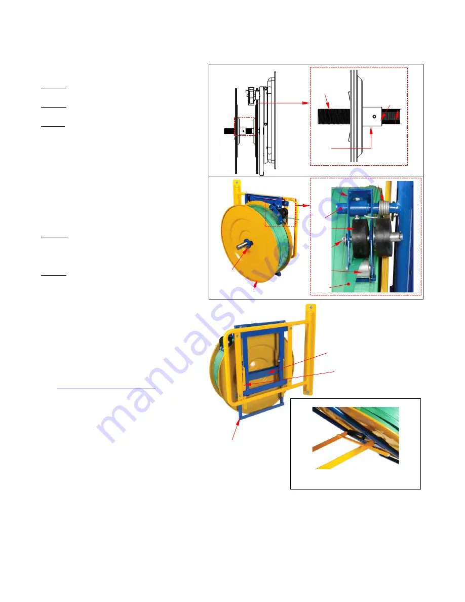
Step 3: Install a selected spool of strapping
material. Orient the spool with the strapping
wound counterclockwise around the spool.
Center the core of the spool on the
threaded rod. Install the rod extension if the
spool of strapping material is wider than 3
inches. To install the extension, wind the rod
coupler onto the end of the threaded rod
and tighten the set screw. Refer to FIG. 1.
NOTE
: The threaded rod will
accommodate spools up to 3 inches
wide.
Step 4: Feed the end of the strapping
material between the upper and lower
rollers of the guide wheel assembly (45-645-
003) as shown in FIG. 2.
Step 5: Reattach the outer retaining disc
and wing nut.
DISPENSING STRAP MATERIAL
Slowly and steadily pull the free end of
the strapping material to dispense it. The
spool holding mechanism (inner and outer
discs and threaded rod) will rotate. Do
not pull quickly and forcefully on the end
of the strap or the spool holder will over
rotate and dispense too much strapping.
To change spools of strapping, follow
on p. 5.
The spool holding assembly can be
used in either of 2 configurations: vertical
and inclined. To incline the assembly, pull
the bottom of the spool frame (45-514-015)
away from the wall. Lift the bottom end of
the yellow support stand (45-514-017). Prop
the free ends of the support stand against
the middle cross brace of the spool frame.
RECORD OF SATISFACTORY CONDITION
Record the condition of the device before putting it into service for the first time. Include
observations about the spool retaining discs, welds, frame elements (frame, support stand, safety chain,
quick link, snap hook, wheels, guide wheel assembly, and strap dispensing mechanisms (collectively
“features”). Thoroughly photograph the unit so that all features are clearly imaged. Take close range
photographs of all labels applied to the unit. Add the photographs to the record. Describe where each
label is located. Collect all photographs and writings in a file. This file is a record of the device in
satisfactory condition. During future inspections, compare your observations to the
RECORD
to
determine if the unit is in satisfactory condition.
FIG. 1
FIG. 2
Rod
extension
Set
screw
T
hreaded
rod
Rod
coupler
Upper
roller
Wing nut
(blue)
Outer retaining disc
Roller
bracket
Roller
pin
Guide wheel
assembly
Spring
Lower
roller
Strap
INCLINED CONFIGURATION
Prop ends of support stand against
middle brace of spool frame
Spool frame
(45-514-015)
Support stand
(45-514-017)
Middle cross
brace
VERTICAL
CONFIGURATION
Guide
wheel
peg


