rev. 3/24/2014
LOW, manual.doc
Copyright 2014 Vestil Manufacturing Corp. 6 of 10
8. Add spacers and washers to the suspension shafts on both sides of the suspension block. Add spacers and
washers so that dimension A in FIG. 2 on p. 5 is
at most
1/16in. longer than half the flange width (calculated
in step 7).
9. Slide the suspension block onto the suspension shafts. Orient the block with the hand chain of the trolley on
the opposite side from the hand chain of the trolley.
10. Add exactly the same number of spacers and washers on the other side of the suspension block.
11. Reinstall the left side plate.
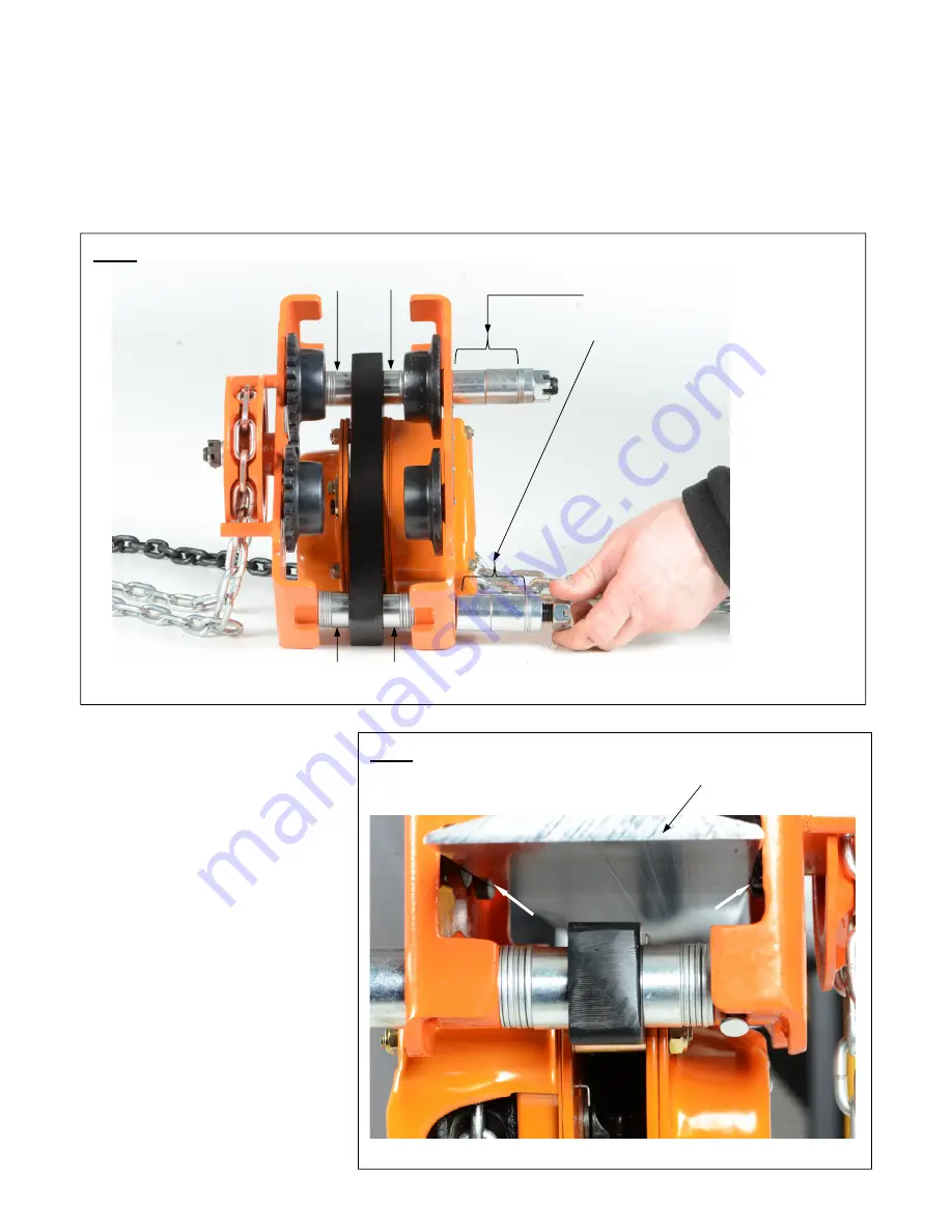
12. Slide the spacers and washers that were removed to the ends of the suspension shafts. Maintain symmetry
when adding spacers and washers, i.e. add the same number and type of spacers/washers to each shaft.
(See FIG. 4)
13. Install the trolley on the lower
flange of the beam. Track rollers
ride on the top of the lower
flange. [NOTE: One end of both
suspension shafts was left
unassembled to allow the trolley
to be installed on the beam
flange.]
14. Reinstall the crown nuts (1) and
washers (2). Tighten the nuts
and secure the connections with
cotter pins (34).
Test the trolley by rolling it several
feet along the beam flange. If
necessary, washers and spacers can
be added symmetrically (on both
sides of both suspension shafts) to
allow the trolley to roll more freely.
However, total clearance between
the edge of the beam flange and the
track roller flanges cannot be more
than 1/8in. (3mm) or 1/16in. per side.
(Shown by white arrows in FIG. 5).
Add the same number and type of
left over spacers and washers to
each suspension shaft
Add the same number and type
of washers and/ or spacers
Add the same number and type
of washers and/ or spacers
FIG. 5:
Install trolley on beam flange
FIG. 4:
Reassembled
trolley
Lower beam flange


