Rev. 2/21/2017
HDC-905, MANUAL
Copyright 2017 Vestil Manufacturing Corp.
Page 1 of 19
HDC-905 Series Hydraulic Drum Crushers
Instruction Manual
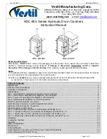
HDC-905-IDC
HDC-905-HC
Receiving instructions:
After delivery, IMMEDIATELY remove the packaging from the product. Then, inspect the unit closely to determine
whether it sustained damage during transport.
If damage is discovered, immediately record a complete
description of the damage on the bill of lading
. If the product is undamaged, discard the packaging.
Notes:
1) Compliance with laws, regulations, codes, and non-voluntary standards enforced in the location where the product
is
used
is exclusively the responsibility of the owner/end-user.
2) VESTIL is
not liable
for any injury or property damage that occurs as a consequence of failing to apply either:
a) Instructions in this manual; or b) information provided on product labels.
Vestil Manufacturing Corp.
2999 North Wayne Street, P.O. Box 507, Angola, IN 46703
Telephone: (260) 665-7586 -or- Toll Free (800) 348-0868
Fax: (260) 665-1339
www.vestilmfg.com
e-mail:
Table of Contents:
Signal Words……………………………………………..……………………………………………………………..………….. 2
Safe Use Recommendations……………..……………………………………………..…………………………..…….……… 2
Hydraulic circuit diagram…….……………………………………………………………………………………………………. 3
Specifications…………………………………..………………………………………………………..…………..…….………. 3
FIG. 1: HDC-905-IDC exploded parts diagram & bill of materials………...……………………………..…………………… 4
FIG. 2: HDC-905-HC exploded parts diagram & bill of materials…………………………………………………………….. 5
FIG. 3: Power unit exploded parts diagram & bill of materials………...…………………..…………………………………..6
FIG. 4: Detailed parts breakdown of manifold assembly………………
……………………………………………………… 7
Manifold, pressure switches, and valves……………….……………………………………………………………………….. 8
Hydraulic valve and pressure switch adjustment procedure………………………………………………………………….. 9
Electrical controls sequence of operation……………………………………………………………………………………… 10
Electrical system specifications…………………………………………………………………………………………………. 10
FIG. 9: Standard 3-phase electrical circuit diagram (22124024 rev. F)…………………………………………………….. 11
FIG. 10: 3-phase continuous run electrical circuit diagram (22124025 rev. C)…………………………………………….. 12
FIG. 11: Single phase 115VAC electrical circuit diagram (22124026 rev. D)……………………………………………….13
FIG. 12: Single phase 208/230VAC electrical circuit diagram (22124027 rev. E)…………………………………………. 14
Installation…………………………………………………………………………………………………………………………. 15
Loading the chamber……………………………………………………………………………………………………………... 15
Operation………….……………………………………………………………………………………………………………….. 15
Platen configurations…………………………………………………………………………………………………………… ... 16
Maintenance………………………………………………………………………………………………………………………. 16
Labeling Diagram…………….....………………………………………………………………………………………………… 17
Limited Warranty (all units
except
“Wash down” model HDC-905-WD)...……………..………………………………..….. 18
Limited Warranty (HDC-905-WD only)…………………………………………………………………………………………. 19


