background image


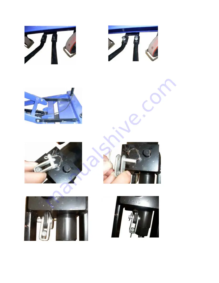
4.2 Foot pedal assembly     


1) Place the foot pedal into the chassis pipe            2) Tighten the bolts 

 
4.3 Lift the platform and place two support bars that will secure and hold the chassis steady. 


4.4. To attach the release handle: 

4.4.1 Connect the chain to the bottom of the pump.   


a) Remove the cotter pins from the axle 


b) Secure the chain into the pump block using cotter pins and the axle.   


4.4.2 Securing the chain into the chassis groove:   

Summary of Contents for CART-550-AS

Page 1: ...Instruction Manual For Auto Shift Hydraulic Lift Table Model Number CART 550 AS Note Owner Operator must read and understand this Instruction Manual before operating the lift tilt table...

Page 2: ...ntents 1 WARNING 2 2 CAUTION 2 3 NAME OF PARTS 3 4 HOW TO ASSEMBLE 4 5 DAILY INSPECTION 6 6 OPERATING LIFTTABLE 6 7 SERVICE INSTRUCTION 7 8 HYDRAULIC CIRCULT 7 9 SPARE PARTS LIST 8 10 TROUBLES SHOOTIN...

Page 3: ...re injury 2 CAUTION 1 Before operating the lift table ensure that you read this operation manual carefully and understand its instructions completely Improper operation could result in injury or prope...

Page 4: ...beginning to assemble A spanner tool and caliper are required when assembling the lift table Clamping tools such as monkey wrenches can also be used Locate these parts for assembly Correctly assembled...

Page 5: ...and place two support bars that will secure and hold the chassis steady 4 4 To attach the release handle 4 4 1 Connect the chain to the bottom of the pump a Remove the cotter pins from the axle b Secu...

Page 6: ...ill activate lift and lower easily when the lift handle is released If the table will not lower please adjust using steps a or b a Loosen the up and down nuts pull the release wire up for a snug fit a...

Page 7: ...t table 2 Check for any cylinder oil leakage 3 Check the vertical creep of the table 4 Check for smooth rotation of the wheel 5 Check for brake function 6 Ensure that all bolts and nuts are tightened...

Page 8: ...st position NOTE The hydraulic cylinder is designed to hold the table As is the nature of the hydraulic system the table lowers very slowly over an extended period of time Please note the table will n...

Page 9: ...8 9 LIFT TABLE SPARE PARTS LIST...

Page 10: ...l 2 20 Steel ball 5 1 72 Pedal bent pipe 1 112 Rod 1 21 Spring base 1 73 Hex screw M8 20 2 113 Rod 1 22 Regulating pressure spring 1 74 Shake link 1 114 Bolt M6 8 1 23 Regulating pressure screw 1 75 S...

Page 11: ...usting the opposite direction 3 The table does not descend A part has been broken or been deformed resulting from unbalanced load The setting screw 58 is not in the correct position Repair or replace...

Page 12: ...nty covers defects in the following original dynamic components motors hydraulic pumps electronic controllers switches and cylinders It also covers defects in original parts that wear under normal usa...

Reviews: