


Page
8
of
15
Assembly Instructions:
As shipped, the cart requires minimal assembly. In
addition to the deck and chassis assembly, you
should receive the following hardware:
- 3 Socket-head cap screws
- 1 L-shaped hex wrench (to tighten bolts)
- 1 Hydraulic pump foot pedal
- 1 Handle assembly
1. Close the release valve by turning it clockwise
until it is snug.
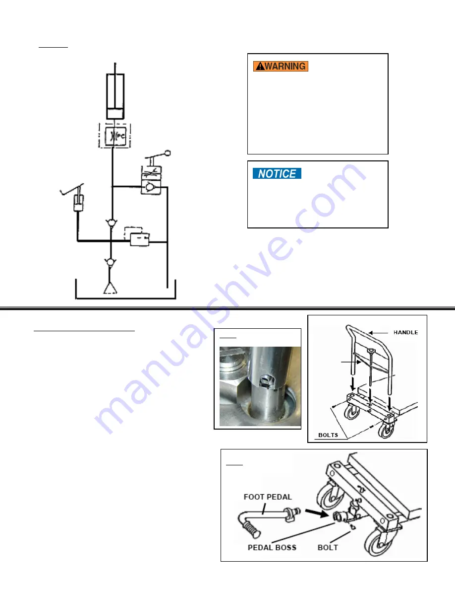
2. Insert the open end of the handle into the
openings in the frame (FIG. 5). Fix the handle
into position using the socket-head cap-
screws and supplied hex-wrench.
3. Insert the end of the pressure relief shaft (item
#245 in FIG. 1; item #252 in FIG. 2) over the
release-valve stem (item #241 in FIG. 1; item
#249 in FIG. 2) The slot in the shaft and the
roll pin on the valve stem must align. Proper
fit is shown in FIG. 5.
4. Attach the foot pedal to the receptacle and
secure the pedal with a socket-head cap-
screw. (see FIG. 6) When properly installed
and secured, the pedal will be able to rotate
90° to the right and left of center allowing the
use of the 2-speed pump feature.
FIG. 3: Hydraulics Diagram
To reduce the
possibility of injury, BEFORE working
on the hydraulic system:
1. Fully lower and secure the deck;
2. Release system pressure and
disconnect all power sources;
3.
DO NOT work on the hydraulic
components UNLESS you are
trained and authorized to do so.
DO NOT use brake
fluid or jack oils in the hydraulic
system. Replace the oil with anti-wear
hydraulic oil having a viscosity of 150
SUS at 100°F (ISO 32 @ 40°C), or
non-synthetic transmission fluid.
FIG. 4:
Spline & Roll Pin
Connection
FIG. 5:
Handle Insertion
VELOCITY FUSE
LOWERING
VALVE
SHELF
FIG. 6:
Pedal Attachment
CYLINDER
PUMP
RELIEF
TANK


