Subject to modifications.
© Vestamatic GmbH
2/2
G
Art.-Nr.:
6000 002 GB 0819 A04 • Vestamatic GmbH • Dohrweg 27 • D-41066 Mönchengladbach
• www.vestamatic.com
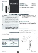
VRS Transmitter 5C / 10C
8. Programming
The transmitter is suitable for all VRS receiver (Vestamatic Radio System).
For more information, please refer to the manual of the used radio receiver.
9. Replacing the Battery
If the hand-held transmitter’s range is dramatically reduced and the LED
indicator is weakly lit, you will need to replace the hand-held transmitter’s
battery.
1. To do this, use a suitable Phillips screwdriver (size 0) to remove the
screw on the back of the hand-held transmitter.
2. Then, press back the snap tab on the top section and remove the
bottom section of the hand-held transmitter.
3. Replace the CR 2032 type battery.
Make sure you insert the new battery correctly, the positive pole
has to be visible.
4. Then reassemble the housing by following the instructions in the reverse
order.
10. Instructions for radio receiver
ATTENTION!
Radio transmission is not suitable for safety operations,
such as emergency-stop, emergency call or warning signals.
Ä
Signals are transmitted across the Europe-wide approved 868 MHz fre-
quency band. The radio transmission range largely depends on the con-
structional circumstances of the building. If other adjacent radio devices are
simultaneously sending signals, mutual interferences cannot be debared.
Such interferences can also affect individual units of a group of receivers.
Observing the following instructions will minimize these interferences:
– Avoid to mount radio receivers onto or adjacent to metal surfaces.
– Maintain minimum 50 cm clearance to consumer loads, such as micro-
wave ovens or TV sets.
– Keep a minimum clearance of 50 cm between each mounted radio
receiver.
– Keep a minimum clearance of 50 cm between a radio receiver and a
radio transmitter.
If a radio-transmitted command cannot be clearly detected, the command
execution will be suppressed by means of an integrated automatic safety
function. The command must then be issued again.
The disposal of electrical equipment and batteries in household waste
is strictly forbidden.
The symbol (dustbin crossed out, in line with WEEE Appendix IX)
indicates separate collection of electrical and electronic products in
EU countries. Do not dispose of the device or battery in your house-
hold waste. Ask your town or local council about the return and col-
lection systems available in your area to dispose of this product.
É
11. Disposal of waste
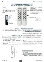
7. Description of radio remote control VRS
A.
LED indication of selected channel of the
transmitter.
To change channel:
Briefly press one of the two channel selection
buttons
+
or . The LEDs show the current
selected channel. Use the button
+
or to
select the channel. The selection is saved im-
mediately.
PROG. button
at the back side
Fu Programming Transmitter
Radio Remote Control VRS
B.
VRS Transmitter 5C (Art.-no. 01580070):
Switching from AUTO to MANUAL mode
(receiver-dependent).
Press and hold the button and then press
the
+
button for 3 seconds until the operat-
ing mode switches. The LEDs AUTO or MAN
and the channels will light up briefly.
VRS Transmitter 10C (Art.-no. 01580080):
Left LED indication channel 1–
5
Right LED indication channel 6
–10
C.
Manual control buttons.
Channel 1–10 = Motor / Shade / Lighting
Button ON/UP =
Q
Button STOP
Button OFF/DOWN =
q
B.
A.
C.


