VESSER WGC18IT/GC18IT Service Manual Download Page 70

WGC-IT / GC-IT   Model: 

18

 - 2

4

Installation and Maintenance

6HUYLFH0DQXDO

6WHSV

3URFHGXUH

3RLQWV

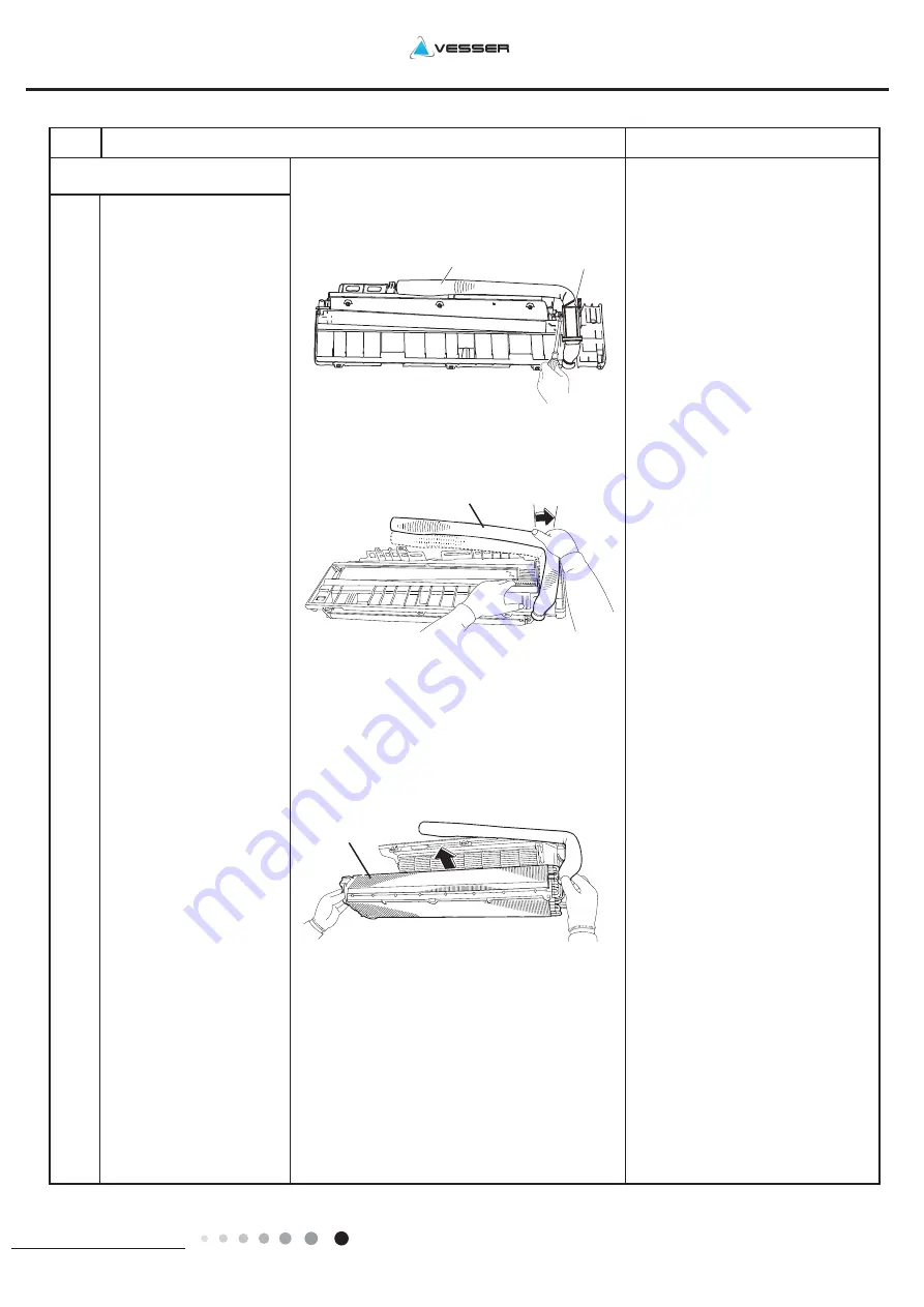
7. Remove piping fixture.

Remove Pipe Clamp

a

Loosen the  screws,

in the right and the left,

which  fix  the  Evaporator 

Assy. Remove  Evaporator  

Assy

b

Auxiliary piping

Piping fixture

Adjust the pipeline slightly

c

Auxiliary  piping

Heat exchanger

Summary of Contents for WGC18IT/GC18IT

Page 1: ...Service Manual R410A Vidicon Ltd Commercial Air Conditioners R410A Systems Models WGC18IT GC18IT WGC24IT GC24IT ...

Page 2: ...VWHP LDJUDP 10 OHFWULFDO 3DUW 11 5 1 Wiring Diagram 11 5 2 PCB Printed Diagram 13 XQFWLRQ DQG RQWURO 15 6 1 Remote Controller Introduction 15 6 2 Brief Description of Modes and Functions 19 3DUW Ċ QVWDOODWLRQ DQG 0DLQWHQDQFH 25 1RWHV IRU QVWDOODWLRQ DQG 0DLQWHQDQFH 25 QVWDOODWLRQ 27 8 1 Installation Dimension Diagram 27 8 2 Installation Parts checking 29 8 3 Selection of Installation Location 29 8...

Page 3: ...alfunction 53 SORGHG 9LHZ DQG 3DUWV LVW 55 10 1 Indoor Unit 55 10 2 Outdoor Unit 59 5HPRYDO 3URFHGXUH 63 11 1 Removal Procedure of Intdoor Unit 63 11 2 Removal Procedure of Outdoor Unit 69 SSHQGL 81 Appendix 1 Reference Sheet of Celsius and Fahrenheit 81 Appendix 2 Configuration of Connection Pipe 81 Appendix 3 Pipe Expanding Method 82 Appendix 4 List of Resistance for Temperature Sensor 83 ...

Page 4: ...YLFH 0DQXDO 6XPPDU 3DUW ĉ 7HFKQLFDO QIRUPDWLRQ QGRRU 8QLW 2XWGRRU 8QLW GC 18 IT GC 24 IT WGC 18 IT WGC 24 IT 5HPRWH RQWUROOHU YB1F2 XFAN FAN AUTO OPER HEALTH AIR FILTER TURBO ON OFF X FAN HOUR HUMIDITY ON OFF MODE FAN X FAN TURBO TEMP TIMER SLEEP LIGHT ...

Page 5: ...wing Motor Model Swing Motor Power Output W Fuse Current A Sound Pressure Level SH H M L SL dB A Sound Power Level SH H M L SL dB A Dimension WXHXD mm Dimension of Carton Box LXWXH mm Dimension of Package LXWXH mm Net Weight kg Gross Weight kg Value WGC18IT GC24IT CB146036000 220 240 50 1 Outdoor 5275 1200 6200 5570 1100 6000 1675 380 2450 1750 350 2600 7 43 7 80 2650 11 80 800 680 560 460 1 8 3 1...

Page 6: ... Isolation I Moisture Protection IP24 Permissible Excessive Operating Pressure for the Discharge Side MPa 4 3 Permissible Excessive Operating Pressure for the Suction Side MPa 2 5 Sound Pressure Level H M L dB A 55 Sound Power Level H M L dB A 65 Dimension WXHXD mm 963X700X396 Dimension of Carton Box LXWXH mm 1026X455X735 Dimension of Package LXWXH mm 1029X458X750 Net Weight kg 46 Gross Weight kg ...

Page 7: ...th LXDXW Swing Motor Model Swing Motor Power Output Fuse Current Sound Pressure Level SH H M L SL Sound Power Level SH H M L SL Dimension WXHXD Dimension of Carton Box LXWXH Dimension of Package LXWXH Net Weight Gross Weight kg Value WGC18IT GC18IT CB146036000 220 240 50 1 Outdoor 5275 1200 6200 5570 1100 6000 1675 380 2450 1750 350 2600 7 43 7 80 2650 11 80 800 680 560 460 1 8 3 15 3 18 5 60 23 3...

Page 8: ...te Type Isolation Moisture Protection Permissible Excessive Operating Pressure MPa for the Discharge Side 4 3 Permissible Excessive Operating Pressure for the Suction Side MPa 2 5 Sound Pressure Level H M L dB A Sound Power Level H M L dB A Dimension WXHXD mm Dimension of Carton Box LXWXH mm Dimension of Package LXWXH mm Net Weight kg Gross Weight kg Refrigerant Refrigerant Charge kg Connection Pi...

Page 9: ...e length 5m Cooling Heating 32 33 34 35 36 37 38 39 43 15 10 5 40 41 42 100 105 95 90 85 80 75 70 65 60 55 50 110 100 90 80 70 60 50 40 0 5 7 10 Conditions Indoor DB27 C WB19 C Indoor air flow Super High Pipe length 5m Conditions Indoor DB20 C WB15 C Indoor air flow Super High Pipe length 5m Outdoor temp C Outdoor temp C Capacity ratio Capacity ratio WGC18 IT 32 33 34 35 36 37 38 39 43 40 41 42 10...

Page 10: ... outdoor unit Inlet and outlet pipe temperature of heat exchanger Fan speed of indoor unit Fan speed of outdoor unit Compressor frequency Hz Indoor Outdoor P MPa T1 C T2 C 20 15 7 6 18K 2 2 to 2 4 70 to 35 2 to 4 Super High High 75 24K 78 QVWUXFWLRQ T1 Inlet and outlet pipe temperature of evaporator T2 Inlet and outlet pipe temperature of condenser P Pressure at the side of big valve Connection pi...

Page 11: ...18 24 Technical Information 6HUYLFH 0DQXDO 2XWOLQH LPHQVLRQ LDJUDP QGRRU 8QLW Φ70 Φ70 70 90 45 45 40 Φ55 Φ55 40 71 161 149 542 176 130 685 193 W D H unit mm 24K Unit 18K Unit Models W H D 18K 867 305 215 24K 1008 319 221 ...

Page 12: ...WGC IT GC IT Model 18 24 Technical Information 6HUYLFH 0DQXDO 2XWGRRU 8QLW Unit mm 24K Unit 18K Unit 963 892 700 396 341 368 560 427 1000 920 610 370 790 395 ...

Page 13: ...pecification Liquid pipe 1 4 6mm Gas pipe 1 2 12mm 18K Gas pipe 5 8 16mm 24K Indoor unit Outdoor unit COOLING HEATING 4 Way valve Discharge Suction Heat exchanger evaporator Heat exchanger condenser Valve Valve Liquid pipe side Gas pipe side Strainer Electric Strainer Capillary or EEV Compressor Accumlator ...

Page 14: ...N Yellow Green BK Black VT Violet OG Orange Note Jumper cap is used to determine fan speed and the swing angle of horizontal lover for this model SENSOR SENSOR AC L BK PE ROOM TUBE M2 SWING UD1 ROOM TEMP RT2 AP2 BN PG YEGN M1 BU FAN MOTOR OUTDOOR UNIT 2 3 XT N 1 TUBE TEMP RT1 SWING MOTOR COM OUT N PGF CAP JUMP DISP2 DISP1 AP1 RECEIVER AND DISPLAY BOARD EVAPORATOR TERMINAL BLOCK L L BU BK BN YEGN P...

Page 15: ... P DC and N DC at AP1 is higher than 30V to prevent the risk of electric shock WARNING BN 20K 15K 50K L2 L2 50K 15K 20K BN WARNING Please don t touch any terminal when the voltage of terminal P DC and N DC at AP1 is higher than 30V to prevent the risk of electric shock POWER θ θ θ COMP L1 W V U PRINTED CIRCUIT BOARD L1 PE YEGN FAN MOTOR 4WAY OFAN VT VT VALVE 4YV 4 WAY M1 PE MAGNETIC PE TERMINAL BL...

Page 16: ...ire 3 Interface of neutral wire 4 Capacitor of fan motor 5 Fuse 6 Interface of PG motor 7 Interface of health function live wire 8 Auto button 9 Up down swing 10 Feedback interface of PG motor 11 Interface of IDU and ODU communication 12 Display interface 13 Jumper cap 14 Interface of tube temperature sensor 15 Interface of ambient temperature sensor 1 2 3 4 5 6 7 8 9 10 11 12 13 14 15 ...

Page 17: ...Terminal of temperature sensor 3 Terminal of electronic expansion valve 4 Terminal of outdoor fan 5 Terminal of 4 way valve 6 Terminal of compressorelectric heating 7 Terminal of chassis electric heating 8 Terminal of indoor unit and outdoor unit communication 9 Power supply live wire 10 Earthing wire 11 Power supply neutral wire 1 2 3 4 5 6 7 8 9 10 11 ...

Page 18: ...TO OPER HEALTH AIR FILTER TURBO ON OFF X FAN HOUR HUMIDITY ON OFF MODE FAN X FAN TURBO TEMP TIMER SLEEP LIGHT 2 10 7 9 12 8 3 11 6 5 13 4 1 Child lock Left right swing Sleep mode Auto mode Air mode Cool mode Heat mode Fan mode Dry mode Up down swing Indoor ambient temp Set temp Outdoor ambient temp FAN OPER AUTO HEALTH AIR FILTER TURBO ON OFF X FAN HOUR HUMIDITY TIMER ON TIMER OFF Set time Light S...

Page 19: ...ontal louvers stops at current position high speed Pressing this button can set fan speed circularly as auto AUTO low medium high Under AUTO Speed IDU fan motor will adjust the fan speed high medium or low speed according to ambient temperature Fan speed under dry mode is low speed Operation indicator is ON ...

Page 20: ...Technical Information 6HUYLFH 0DQXDO no display no display swing angle is displayed dynamically horizontal louvers stops at current position swing angle is displayed dynamically This function is applicable to partial of models ...

Page 21: ...WGC IT GC IT Model 18 24 Technical Information 6HUYLFH 0DQXDO Signal sender Battery Cover of battery box Remove Reinstall ...

Page 22: ...n for the compressor is reached the compressor and the outdoor fan motor stop operation The upper down horizontal louver will rotate to the horizontal position L The indoor fan will be stopped after operating for 60s at setting speed b Due to the blockage of PG motor horizontal louver will keep the stop position when the unit is turned off In other modes When the unit is stopped due to other malfu...

Page 23: ...p the sleep function the temperature will increase by1 C every one hour After the temperature has increased by 3 C the unit will keep this temperature When the unit has operated for 7 hours the temperature will decrease by 1 C and then the unit will operate at this temperature all the time ĸ When the initial temperature is set as 24 27 C after starting up the sleep function the temperature will in...

Page 24: ...e detected at any other time 3URWHFWLRQ RI WHPSHUDWXUH VHQVRU 1 When the temperature sensor is detected short circuit for 5s successively The detected temperature by the temperature sensor is too high and the complete unit will stop operation meanwhile the protection and malfunction of temperature sensor will be displayed accordingly 2 When the temperature sensor is detected open circuit for 5s su...

Page 25: ...t 25 30 C Cooling at low temperature that is the minimum setting temperature for outdoor unit judgment is 25 C U 0RGH ķ Conditions and processes of dry operations Same as the cooling mode ĸ The temperature setting range is 16 30 C 3 Fan Mode 1 The compressor outdoor fan and four way valve are switched off ĸ The temperature setting range is 16 30 C HDWLQJ 0RGH ķ Conditions and processes of heating ...

Page 26: ...essor may decrease or the operation frequency of compressor may stop increasing Ĺ If the unit stops operation due to freeze prevention protection for 6 times successively the unit cant resume operation automatically and error code will be displayed successively Only press ON OFF button can resume the operation During operation process if compressor operates for more than 10min times of stop operat...

Page 27: ... modular protection signal Main chip will detect the modular protection signal as soon as the unit is turned on Once modular protection signal is detected the unit will stop operation immediately due to protection If modular protection is resumed and compressor has stopped for 3min the complete unit can then be allowed to resume operation If the unit stops operation due to modular protection for 3...

Page 28: ...G PDLQWHQDQFH DYH WKH XQLW DGHTXDWHO JURXQGHG 7KH JURXQGLQJ ZLUH FDQ W EH XVHG IRU RWKHU SXUSRVHV 0XVW DSSO SURWHFWLYH DFFHVVRULHV VXFK DV SURWHFWLYH ERDUGV FDEOH FURVV ORRS DQG ZLUH FOLS 7KH OLYH ZLUH QHXWUDO ZLUH DQG JURXQGLQJ ZLUH RI SRZHU VXSSO PXVW EH FRUUHVSRQGLQJ WR WKH OLYH ZLUH QHXWUDO ZLUH DQG JURXQGLQJ ZLUH RI WKH DLU FRQGLWLRQHU 7KH SRZHU FRUG DQG SRZHU FRQQHFWLRQ ZLUHV FDQ W EH SUHVVH...

Page 29: ...QDQFH HYHO PHWHU PHDVXULQJ WDSH OHFWURSUREH OHFWURQLF OHDNDJH GHWHFWRU 3LSH SOLHUV SLSH FXWWHU 6FUHZ GULYHU 8QLYHUVDO PHWHU 9DFXXP SXPS 3LSH H SDQGHU SLSH EHQGHU PSDFW GULOO GULOO KHDG HOHFWULF GULOO 7RUTXH ZUHQFK RSHQ HQG ZUHQFK LQQHU KH DJRQ VSDQQHU 3UHVVXUH PHWHU 6ROGHULQJ DSSOLDQFH UHIULJHUDQW FRQWDLQHU ...

Page 30: ...cm At least 15cm At least 15cm At least 250cm Space to the wall S p a c e t o t h e o b s t r u c t i o n r o o l f e h t o t e c a p S Space to the obstruction Drainage pipe Space to the wall Space to the obstruction Space to the obstructio Space to the obstruction A t l e a s t 3 0 0 c m At least 50cm At least 200cm At least 30cm At least 30cm At least 50cm ...

Page 31: ...hang the indoor unit Make the bound pipes pass through the wall hole and then connect outdoor unit Neaten the pipes Vacuum pumping and leakage detection Check after installation and test operation Finish installation Note this flow is only for reference please find the more detailed installation steps in this section Select outdoor unit installation location Install the support of outdoor unit sel...

Page 32: ...er is first class electric appliance It must be properly grounding with specialized grounding device by a professional Please make sure it is always grounded effectively otherwise it may cause electric shock 2 The yellow green wire in air conditioner is grounding wire which can t be used for other purposes 3 The grounding resistance should comply with national electric safety regulations 4 The appl...

Page 33: ...lected outlet pipe position In order to drain smoothly slant the piping hole on the wall slightly downward to the outdoor side with the gradient of 5 10 As show in Fig 2 1RWH Insulating pipe Torque wrench Open end wrench Indoor pipe Pipe Union nut Union nut Pipe joint Pipe Hex nut diameter mm Tightening torque N m Φ6 15 20 Φ9 52 30 40 Φ12 45 55 Φ16 60 65 Φ19 70 75 Refer to the following table for ...

Page 34: ...ertain length of drain hose and power cord for installation when binding them When binding to a certain degree separate the indoor power and then separate the drain hose As show in Fig 15 3 Bind them evenly 4 The liquid pipe and gas pipe should be bound separately at the end 2 Make the power connection wire go through the cable cross hole at the back of indoor unit and then pull it out from the fr...

Page 35: ...nit with bolts As show in Fig 20 RQQHFW QGRRU DQG 2XWGRRU 3LSHV 1 Remove the screw on the handle and valve cover of outdoor unit and then remove the handle and valve cover As show in Fig 21 2 Remove the screw cap of valve and aim the pipe joint at the bellmouth of pipe As show in Fig 22 3 Pretightening the union nut with hand 4 Tighten the union nut with torque wrench Fig 18 Fig 19 Fig 20 Fig 21 F...

Page 36: ...to the refrigerant charging vent of gas valve and then connect the other charging hose to the vacuum pump 3 Open the piezometer completely and operate for 10 15min to check if the pressure of piezometer remains in 0 1MPa 4 Close the vacuum pump and maintain this status for 1 2min to check if the pressure of piezometer remains in 0 1MPa If the pressure decreases there may be leakage 5 Remove the pi...

Page 37: ...ture sensor is open short circuited F1 Indoor evaporator temperature sensor is open short circuited F2 Module temperature sensor is open short circuited P7 Outdoor ambient temperature sensor is open short circuited F3 Outdoor condenser tube temperature sensor is open short circuited F4 Outdoor discharge temperature sensor is open short circuited F5 Communication malfunction between indoor and outd...

Page 38: ... for 30s and then peformedischarging NOTE A large capacity electrolytic capacitor is used in the outdoor unit controller inverter Therefore if the power supply is turned off charge charging voltage DC280V to 380V remains and disc harging takes a lot of time After turning off the power source if touching the charging section before discharging an electrical shock may be caused Discharge the electro...

Page 39: ...ndthe controller loosened or poorly contacted Insert the temperature sensor tightly yes Is malfunction eliminated Is there short circuit due to trip over of the parts Make the parts upright yes Is malfunction eliminated Replace the mainboard with the same model End no no Is the temperature sensor normal according to the Resistance Table no Replace it with a temperature sensor with the same model n...

Page 40: ... motor correctly Is malfunction eliminated No No Turn on the unit again measure whether the output voltage on control terminal for PG motor is more than 50V within 1 min after the louvers are opened No Is the motor started up No Is malfunction eliminated No Is malfunction eliminated Tighten the screw reassemble the blade motor and shaft bearing rubber base sub assy to make sure there is no foreign...

Page 41: ... the mainboard Is the jumper cap inserted correctly and tightly Replace the jumper cap with the same model End Yes Assemble the jumper cap with the same model No Is malfunction eliminated No Insert the jumper cap tightly Is malfunction eliminated No No Is malfunction eliminated No Replace the mainboard with the same model Yes Yes Yes Yes expl model 12 short x open o nr 1 2 3 4 5 set o x x x o ...

Page 42: ...ng to the wiring diagram Is malfunction eliminated Is malfunction eliminated Is malfunction eliminated Is malfunction eliminated Main board matches with display board Main board of IDU matches with that of ODU Match correctly according to product specification Connection of communication wire is damaged or not Replace the connection wire Replace the main board of IDU Replace the main board of ODU ...

Page 43: ...shooting for U8 malfunction Re energize1 minute after de erergization U8 is still displayed The unit returns to normal Conclusion U8 is displayed due to instant energization afte de energization while the capacitor discharges slowly The zero cross detection circuit of the mainboard is defined abnormal Replace the mainboard with the same model End No Yes ...

Page 44: ...ion occurs after de energizing and turning on the unit Whether stop time for compressor is more than 3min No No No No No No No Yes Yes Yes Yes Yes No Yes Yes Yes Yes Whether valve of outdoor unit is opened Whether wire connection for compressor is correct Open the valve Is malfunction eliminated Connect wire correctly Is malfunction eliminated Replace electronic expansion valve Is malfunction elim...

Page 45: ...or the unit such as clean heat exchanger improve ventilation etc Turn on the unit again after the power voltage is resumed Charge refrigerant according to service manual Whether the outdoor fan can operate normally Whether the radiation for the unit is in good condition Whether the input voltage is normal Whether refrigerant is superfluous Replace main board of outdoor unit Is malfunction eliminate...

Page 46: ...is damaged KHFN ÀRZ FKDUW Start the troubleshooting for temperature sensor Check the connection between temperature sensor and wiring terminal is loose or in poor connection Check whether the temperature sensor is normal according to the Resistance Value Table for Temperature Sensor Insert the temperature sensor well Is malfunction eliminated Is malfunction eliminated Replace the temperature senso...

Page 47: ... ambient temperature Whether the resistance 1KΩ Whether wire connection wire electronic expansion valve is in good condition Check the coil of electronic expansion valve If it s damaged please replace it Is malfunction eliminated If the refrigerant is leaking please add refrigerant according to Service Manual Is malfunction eliminated Replace main board of outdoor unit End Yes Yes Yes Yes No No No...

Page 48: ...ait for 1 min There is malfunction for the detection circuit on main board of outdoor unit Check the input power and resume the power supply normal Is malfunction eliinated Measure the voltage at both ends of big electrolytic capacitor with the DC notch of universal meter Is the voltage more than 100V Check whether the input voltage is within the normal range Replace main board of outdoor unit End...

Page 49: ... fan terminal is connected well Whether the fan is damaged Replace fan capacitor unavailable for DC fan Replace outdoor fan Whether outdoor ambient temperature is more than 53o C Whether radiation inside or outdoor the unit is good Whether outdoor fan operates normally Replace main board of outdoor unit End No Yes Yes Yes Yes No No No Remark When overload protection occurs under cooling mode it s ...

Page 50: ...compressor wires are connected correctly Whether there re above circumstances Connect compressor wires according to correct wiring method Modify it according to Service Manual and then energize and turn on the unit Measure the resistance beween two phases of three phases of compressor Is resistance value normal Measure the resistance between three phase of compressor and copper pipe Is resistance ...

Page 51: ...YLFH 0DQXDO 0DOIXQFWLRQ RI 3 3URWHFWLRQ 0DLQ FKHFN SRLQW Whether power supply is normal KHFN ÀRZ FKDUW Start Check whether power supply is normal Is power abnormal Replace main board of outdoor unit End Turn on the unit again after the power is resumed Yes No ...

Page 52: ...nit or main board of outdoor unit is damaged KHFN ÀRZ FKDUW Communication malfunction De energize the unit and then check whether connection wires between indoor unit and outdoor unit and wiring inside the electric box are correct Are wires are connected correctly Replace main board of indoor unit Is malfunction eliminated End Replace main board of outdoor unit Connect wire correctly according to ...

Page 53: ...e stop time for compressor is more than 3min Whether compressor wires are connected correctly The stop time for unit is not enough high pressure and low pressure of system are unbalanced please wait for 3min and then restart up the unit Whether the refrigerant volume is superfluous Please charge the refrigerant according to Service Manual Is malfunction eliminated Replace main board of outdoor unit...

Page 54: ...re of the shell too high etc Is the indoor outdoor heat exchanger too dirty or are the air inlet and outlet blocked Normal fluctuation is within 10 of the rated voltage on the nameplate Malfunction is eliminated No Yes No Yes No Yes No No No yes No Yes No Yes Yes Yes Yes Yes Yes Yes Malfunction is eliminated Malfunction is eliminated Malfunction is eliminated Malfunction is eliminated Malfunction ...

Page 55: ...or fan etc HWHFWLRQ FLUFXLW PDOIXQFWLRQV RI SKDVH FXUUHQW RI FRPSUHVVRU 8 Hardware of main board is damaged Please replace main board EXVEDU YROWDJH LV WRR KLJK 3 ķ Input voltage is too high or unstable ĸ Hardware of main board is damaged EXVEDU YROWDJH LV WRR ORZ 3 ķ Input voltage is too low or unstable ĸ Hardware of main board is damaged 0DOIXQFWLRQ RI 2 8 IDQ ķ The wire terminal of outdoor fan ...

Page 56: ...4 of maintenance method for details Malfunction of compressor Compressor can t operate Refer to point 5 of maintenance method for details 7URXEOHVKRRWLQJ IRU 1RUPDO 0DOIXQFWLRQ LU RQGLWLRQHU DQ W EH 6WDUWHG 8S 3RRU RROLQJ HDWLQJ IRU LU RQGLWLRQHU RUL RQWDO RXYHU DQ W 6ZLQJ Possible Causes Discriminating Method Air conditioner Status Troubleshooting No power supply or poor connection for power plug...

Page 57: ...nit or there re parts touching together inside the outdoor unit There s abnormal sound fro outdoor unit Remove foreign objects Adjust all parts position of outdoor unit tighten screws and stick damping plaster between connected parts Short circuit inside the magnetic coil During heating the way valve has abnormal electromagnetic sound Replace magnetic coil Abnormal shake of compressor Outdoor unit...

Page 58: ...SORGHG 9LHZ DQG 3DUWV LVW QGRRU 8QLW FAN AUTO OPER HEALTH AIR FILTER TURBO ON OFF X FAN HOUR HUMIDITY ON OFF MODE FAN X FAN TURBO TEMP TIMER SLEEP LIGHT 13 39 38 37 12 11 10 9 8 7 6 5 4 22 21 20 19 18 17 16 15 14 23 24 25 26 27 29 31 30 32 33 34 35 36 28 3 2 1 WGC 18 IT ...

Page 59: ... Box Assy 1 25 Electric Box 1 26 Axile Bush 1 27 Indicator Light Cover 1 28 Indicator shield cover 1 29 Terminal Board 1 30 Jumper 1 31 Electric Box Cover2 1 32 Main Board 1 33 Display Board 1 34 Shield Cover of Electric box Cover 1 35 Electric Box Cover 1 36 Shield cover of Electric Box 1 37 Power Cord 38 Connecting Cable 0 39 Remote Controller Part Code WGC 18 IT 1 Above data is subject to chang...

Page 60: ...ance 6HUYLFH 0DQXDO 37 36 35 14 12 11 10 13 8 28 29 24 16 25 9 15 17 18 19 6 22 23 5 27 3 4 2 1 20 21 7 30 32 33 26 31 34 FAN AUTO OPER HEALTH AIR FILTER TURBO ON OFF X FAN HOUR HUMIDITY ON OFF MODE FAN X FAN TURBO TEMP TIMER SLEEP LIGHT 38 WGC 24 IT ...

Page 61: ... Motor 1 21 Crank 1 22 Guide Louver 1 23 Axile Bush 2 24 Electric Box 1 25 Terminal Board 1 26 Main Board 1 27 Electric Box Cover2 1 28 Shield Cover of Electric box Cover 1 29 Electric Box Cover 1 30 Indicator shield cover 1 31 Indicator Light Cover 1 32 Display Board 1 33 Shield cover of Electric Box 1 34 Electric Box Assy 1 35 Power Cord 36 Connecting Cable 0 37 Remote Controller 1 38 Cold Plasm...

Page 62: ...WGC IT GC IT Model 18 24 Installation and Maintenance 6HUYLFH 0DQXDO 2XWGRRU 8QLW 22 9 8 7 6 4 2 1 16 14 13 12 11 20 19 18 17 23 25 26 27 32 31 29 3 5 28 30 21 15 10 24 GC 18 IT ...

Page 63: ... 0713506703 0713506703 1 12 Cut off Valve 0713506803 0713506803 1 13 Handle 26235254 26235254 1 14 Magnet Coil 4300040045 4300040045 1 15 Wiring Clamp 26115004 26115004 1 16 Temperature Sensor 3900030901 3900030901 1 17 Rear Grill 01473043 01473043 1 18 Condenser Assy 01163935 01163935 1 19 Clapboard Assy 01233153 01233153 1 20 Coping 01255005P 01255005P 1 21 Supporting Board Condenser 01795010 01...

Page 64: ...WGC IT GC IT Model 18 24 Installation and Maintenance 6HUYLFH 0DQXDO 1 2 3 4 5 6 7 8 9 10 11 12 13 14 15 16 17 18 19 20 21 22 23 24 25 26 27 28 29 30 31 32 33 35 34 36 37 GC 24 IT ...

Page 65: ...14 Cut off Valve 07133157 07133157 1 15 Baffle alve Support 01365435P 01365435P 1 16 Right Side Plate 0130504401P 0130504401P 1 17 Valve Cover 22245003 22245003 1 18 Big Handle 26235001 26235001 1 19 Wiring Clamp 26115004 26115004 1 20 Rear Grill 01475013 01475013 1 21 Condenser Assy 01163917 01163917 1 22 Reactor 23 Clapboard Assy 01233164 01233164 1 24 Condenser Support Plate 01175092 01175092 1...

Page 66: ...s 2 Removing air filters If ON OFF button is kept pushing for 5 seconds a forced cooling operation will be carried out for ap prox 15 minutes Pull protrusions on left and right sides of panel with fingers and open front panel all the way a Lift center section of air filter and disengage hooks b Left and right filters are interchangeable To re install insert air filter along the guide Remove air filter b...

Page 67: ...er by the other hand Draw out the axial bush Bend the horizontal louver slightly and then remove it a Left and right filters are interchangeable To re install insert air filter along the guide Hook a finger onto the projection part provided on the both sides of the units panel and open up the panel to the position higher than it will stop b Remove the front panel from the unit c Guide Louver axial bu...

Page 68: ...ded At the upper part there are 2 hooks in the left and the right Remove the 5 screws in the right and the left which fix the main body with the front grille a Disengage the hooks by pressing knobs with a screwdriver Disengage the 3 hooks on the upper part In case that the hooks are not pressed from above remove the front panel and then remove the grille while pushing the hook through a clearance b...

Page 69: ...Sensor Disconnect the connection wires Twist off the earthing screw fixing the evaporator Pull out the all the wiring terminals b Pay attention to the direction of the retainer of the thermistor so that the retainer will not touch the harness same as the existing models Terminal board Connecting wires Heat exchanger thermistor Remove a screw on the electrical box c ...

Page 70: ...DQXDO 6WHSV 3URFHGXUH 3RLQWV 7 Remove piping fixture Remove Pipe Clamp a Loosen the screws in the right and the left which fix the Evaporator Assy Remove Evaporator Assy b Auxiliary piping Piping fixture Adjust the pipeline slightly c Auxiliary piping Heat exchanger ...

Page 71: ...the pressure plate of motor 9 Remove shaft cushion rubber base Remove screws of motor press plate and then remove the motor press plate Pressure plate of motor Shaft cushion rubber base Remove motor blade and shaft cushion rubber base Remove screws on cross flow blade and then remove the motor Screw a b ...

Page 72: ...panel the 3 screws connecting the top panel with the front panel and the right side plate and then remove the top panel 2 Remove grille panel and rear grill Remove the 2 screws connecting the grille and the panel and then remove the grille 6WHSV 3URFHGXUH 5HPRYDO 3URFHGXUH RI 2XWGRRU 8QLW DUQLQJ H VXUH WR ZDLW IRU D PLQLPXP RI PLQXWHV DIWHU WXUQLQJ RII DOO SRZHU VXSSOLHV DQG GLVFKDUJH WKH UHIULJHU...

Page 73: ...he chassis and the motor support and then remove the panel 3 Remove left side plate and right side plate Remove the screws connecting the right side plate with the chassis the valve support and the electric box and then remove the right side plate assy Remove the screws connecting the left side plate and the chassis and then remove the left side plate assy panel rear grill right side plate leftsid...

Page 74: ...ut the wiring terminals and then pull the electric box upwards to remove it Remove the 4 tapping screws fixing the motor disconnect the leading wire insert of the motor and then remove the motor Remove the 2 tapping screws fixing the motor support and then pull the motor support upwards to remove it Remove the nuts fixing the blade and then remove the axial flow blade axial flow blade electric box...

Page 75: ...oundproof sponge carefully soundproof sponge 7 Remove Isolation sheet Remove the 3 screws fixing the isolation sheet and then remove the Isolation sheet Isolation sheet 8 Remov e 4 way valve assy Discharge the refrigerant completely unsolder the pipelines connecting the compressor and the condenser assy and then remove the 4 way valve assy 4 way valve assy 6WHSV 3URFHGXUH ...

Page 76: ...remove the compressor Remove the screws connecting the support condenser and condenser assy and then remove the support condenser 9 Remov e compressor compressor 10 Remove condenser sub assy 1 support capillary sub assy 2 Remove the chassis sub assy and condenser sub assy condenser sub assy chassis sub assy 6WHSV 3URFHGXUH ...

Page 77: ...WGC IT GC IT Model 18 24 Installation and Maintenance 6HUYLFH 0DQXDO 2 Dissemble the chassis sub assy and condenser sub assy condenser sub assy chassis sub assy 6WHSV 3URFHGXUH ...

Page 78: ...nel Remove the 3 screws connecting the top panel with the front panel and the right side plate and then remove the top panel top panel 2 Remove grille front side plate and panel Remove Remove the 1 screw connecting the front side plate and the panel and then remove the front side plate the 2 screws connecting the grille and the panel and then remove the grille 2 handle and valve cover grille front...

Page 79: ...move the panel 3 Remove right side plate and left side plate Remove the screws connecting the right side plate with the chassis the valve support and the electric box and then remove the right side plate assy panel rightsideplate Remove the screws connecting the left side plate and the chassis and then left side plate remove the left side plate assy 6WHSV 3URFHGXUH ...

Page 80: ...l out the wiring terminals and then pull the electric box upwards to remove it Remove the 4 tapping screws fixing the motor disconnect the leading wire insert of the motor and then remove the motor Remove the 2 tapping screws fixing the motor support and then pull the motor support upwards to remove it electric box fan motor axial flow blade Remove the nuts fixing the blade and then remove the axi...

Page 81: ...move the soundproof sponge carefully 7 Remove Isolation sheet Remove the 3 screws fixing the isolation sheet and then remove the Isolation sheet Isolation sheet Discharge the refrigerant completely unsolder the pipelines connecting the compressor and the condenser assy and then remove the 4 way valve assy 4 way valve assy 4 way valve assy Connection Pipe 6WHSV 3URFHGXUH ...

Page 82: ...emove the 2 bolts fixing the valve subassemblies Unsolder the welding joint connecting the gas valve and the return air pipe Remove the gas valve Note When unsoldering the soldering joint wrap the gas valve with wet cloth completely to avoid damage to the valve caused by high temperature Unsolder the welding joint connecting the liquid valve and the connecting pipe Remove the liquid valve Remove s...

Page 83: ...WGC IT GC IT Model 18 24 Installation and Maintenance 6HUYLFH 0DQXDO 11 Remove condenser sub assy Remove the chassis sub assy and condenser sub assy chassis sub assy condenser sub assy 6WHSV 3URFHGXUH ...

Page 84: ...6 55 4 13 79 80 78 8 26 34 35 33 8 1 57 58 57 2 14 81 80 6 27 36 35 6 2 59 60 59 15 82 83 82 4 28 37 38 37 4 3 61 62 60 8 16 84 85 84 2 29 39 40 39 2 4 63 62 6 17 86 87 86 30 41 42 41 5 64 65 64 4 18 88 89 87 8 31 43 44 42 8 6 66 67 66 2 19 90 89 6 32 45 44 6 7 68 69 68 20 91 92 91 4 33 46 47 46 4 8 70 71 69 8 21 93 94 93 2 34 48 49 48 2 9 72 71 6 22 95 96 95 35 50 51 50 10 73 74 73 4 23 97 98 96 ...

Page 85: ...LQJ WR WKH IROORZLQJ VWHSV A Cut the pip Confirm the pipe length according to the distance of indoor unit and outdoor unit Cut the required pipe with pipe cutter B Remove the burrs Remove the burrs with shaper and prevent the burrs from getting into the pipe C Put on suitable insulating pipe D Put on the union nut Remove the union nut on the indoor connection pipe and outdoor valve install the unio...

Page 86: ...758 6 66 88 33 10 63 72 2 439 111 0 737 5 63 46 34 10 2 73 2 358 112 0 717 4 60 23 35 9 779 74 2 28 113 0 697 3 57 18 36 9 382 75 2 206 114 0 678 2 54 31 37 9 003 76 2 133 115 0 66 1 51 59 38 8 642 77 2 064 116 0 642 0 49 02 39 8 297 78 1 997 117 0 625 1 46 6 40 7 967 79 1 933 118 0 608 2 44 31 41 7 653 80 1 871 119 0 592 3 42 14 42 7 352 81 1 811 120 0 577 4 40 09 43 7 065 82 1 754 121 0 561 5 38...

Page 87: ...3 252 111 0 983 5 84 61 34 13 59 73 3 144 112 0 956 4 80 31 35 13 04 74 3 04 113 0 93 3 76 24 36 12 51 75 2 94 114 0 904 2 72 41 37 12 76 2 844 115 0 88 1 68 79 38 11 52 77 2 752 116 0 856 0 65 37 39 11 06 78 2 663 117 0 833 1 62 13 40 10 62 79 2 577 118 0 811 2 59 08 41 10 2 80 2 495 119 0 77 3 56 19 42 9 803 81 2 415 120 0 769 4 53 46 43 9 42 82 2 339 121 0 746 5 50 87 44 9 054 83 2 265 122 0 72...

Page 88: ... 5 23 53 74 62 11 32 101 3 22 15 362 9 24 51 41 63 10 93 102 3 13 14 342 8 25 49 19 64 10 54 103 3 04 13 323 9 26 47 08 65 10 18 104 2 96 12 306 2 27 45 07 66 9 83 105 2 87 11 289 6 28 43 16 67 9 49 106 2 79 10 274 29 41 34 68 9 17 107 2 72 9 259 3 30 39 61 69 8 85 108 2 64 8 245 6 31 37 96 70 8 56 109 2 57 7 232 6 32 36 38 71 8 27 110 2 50 6 220 5 33 34 88 72 7 99 111 2 43 5 209 34 33 45 73 7 73 ...

Page 89: ...Vidicon Ltd Commercial Air Conditioners R410A Systems ...

Reviews: