29
VXR-7000 UHF Service Manual
Alignment
Set up the test equipment as shown below, and apply
AC power to the repeater.
The repeater must be programmed for use in the in-
tended system before alignment is attempted. The frequen-
cy and other parameters are loaded from the file during
the alignment process.
In order to facilitate alignment over the complete
switching range of the equipment it is recommended that
the channel data first be uploaded and then stored to disk.
Channels at the upper, lower and middle band edges should
then be downloaded. The original data can be replaced at
the end of the alignment process.
Channel
Frequency (MHz)
Ver. D
Ver. A
Ver. BS1
Low band edge 450.000
400.000
420.000
Center
465.000
415.000
435.000
High band edge 480.000
430.000
450.000
Transmitter
Press the
BASE/REPEATER
switch on the front panel
of the repeater so as to set it to the
“
BASE
”
mode if the
REPEATER
LED is on. You should see the
REPEAT-
ER
LED turn off, indicating that the repeater is now in
the “
BASE
” mode.
PLL VCV (Varactor Control Voltage) Check
Connect the DC voltmeter between the VCV check
point (on the TX Unit) and chassis ground.
Select the Low band edge channel, then key the re-
peater. Confirm that the DC voltmeter reading is 0.6
~ 1.5 VDC (TYP D) or 1.5 ± 0.3 VDC (TYP A) or
1.2 ~ 1.8 VDC (TYP BS1).
Select the High band edge channel, then key the re-
peater. Confirm that the DC voltmeter reading is 3.8
~ 4.5 VDC (TYP D) or 3.6 ± 0.4 VDC (TYP A) or
3.2 ~ 4.0 VDC (TYP BS1).
PLL Reference Frequency Adjustment
Select the Center channel, then key the repeater.
Adjust
TC2001
(on the TX unit), if necessary, so
that the frequency counter reading is within ±100Hz
of the programmed Center channel frequency.
Transmitter parameters (excluding PLL)
The following transmitter parameters can be adjust-
ed from the computer by utilizing the CE27 Chan-
nel/Alignment Program. Refer to the onboard help
of the CE27 Channel/Alignment Program for details.
TX Parameters
Data
TX Power Level (High)
0 (00h) ~ 255 (FFh)
TX Power Level (Low)
0 (00h) ~ 255 (FFh)
Maximum Deviation
0 (00h) ~ 255 (FFh)
CTCSS Deviation
0 (00h) ~ 255 (FFh)
DCS Deviation
0 (00h) ~ 255 (FFh)
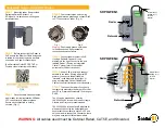
Alignment Setup
TX Unit Alignment Points
VCV Check Point
TC2001
Summary of Contents for VXR-7000
Page 21: ...21 VXR 7000 UHF Service Manual Block Diagram ...
Page 22: ...22 VXR 7000 UHF Service Manual Block Diagram ...
Page 23: ...23 VXR 7000 UHF Service Manual Block Diagram ...
Page 24: ...24 VXR 7000 UHF Service Manual Interconnection Diagram ...
Page 32: ...32 VXR 7000 UHF Service Manual Note ...
Page 36: ...36 VXR 7000 UHF Service Manual PA Unit Lot 1 61 Replaced by PA 2 Unit Note ...
Page 42: ...42 VXR 7000 UHF Service Manual PA 2 Unit Lot 62 Note ...
Page 44: ...44 VXR 7000 UHF Service Manual PA 2 Unit Lot 62 Parts Layout Side B 2 1 a c e f d b g h i 3 ...
Page 52: ...52 VXR 7000 UHF Service Manual TX Unit Lot 1 59 Replaced by TX 2 Unit Note ...
Page 58: ...58 VXR 7000 UHF Service Manual TX 2 Unit Lot 60 Note ...
Page 60: ...60 VXR 7000 UHF Service Manual TX 2 Unit Lot 60 Note ...
Page 66: ...66 VXR 7000 UHF Service Manual TX 2 Unit Lot 60 Note ...
Page 70: ...70 VXR 7000 UHF Service Manual RX Unit Lot 1 59 Replaced by RX 2 Unit Note ...
Page 78: ...78 VXR 7000 UHF Service Manual RX 2 Unit Lot 60 Note ...
Page 80: ...80 VXR 7000 UHF Service Manual RX 2 Unit Lot 60 Note ...
Page 90: ...90 VXR 7000 UHF Service Manual CNTL Unit Note ...
Page 104: ...104 VXR 7000 UHF Service Manual CNTL Unit Note ...
Page 105: ...105 VXR 7000 UHF Service Manual Circuit Diagram Lot 1 107 Display Unit ...
Page 107: ...107 VXR 7000 UHF Service Manual Circuit Diagram Lot 108 Display Unit ...
Page 112: ...112 VXR 7000 UHF Service Manual Display Unit Note ...
Page 117: ...117 VXR 7000 UHF Service Manual Key Unit Circuit Diagram Lot 108 ...
Page 120: ...120 VXR 7000 UHF Service Manual Key Unit Note ...
Page 122: ...122 VXR 7000 UHF Service Manual Key Unit Note ...
Page 124: ...124 VXR 7000 UHF Service Manual Filter Unit 50W Type Note ...
Page 130: ...130 VXR 7000 UHF Service Manual Filter 2 Unit 25W Type Note ...
Page 136: ...136 VXR 7000 UHF Service Manual SW Unit 25W Type Note ...
Page 141: ...141 PS Unit VXR 7000 UHF Service Manual Circuit Diagram ...
Page 145: ...145 VXR 7000 UHF Service Manual ...


