


Correct alignment requires that the ambient temperature be the same as that of the transceiver and
test equipment, and that this temperature be held constant between 20 and 30
℃
(68~86F). When
the transceiver is brought into the shop from hot or cold air it should be allowed some time for
thermal equalization with the environment before alignment. If possible, alignments should be made
with oscillator shields and circuit boards firmly affixed in place. Also, the test equipment must be
thoroughly warmed up before beginning.
Before beginning, connect the transceiver and PC using the CT-71 programming cable as described
in the EEPROM Programming chapter, and download the EEPROM data from the transceiver to the
computer.
Store this data in a disk file so that it can be saved and retrieved later. Using the table below,
program the channel, CTCSS, and DCS alignment settings for your transceiver version. Upload this
file to the transceiver.
Note: Signal levels in dB referred to in this procedure are based on 0 dBm = 0.5 mV(terminated
circuit).
Caution:
Caution:
Caution:
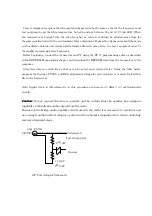
Caution: Do not connect this line to ground, and be certain that the speaker has adequate
capability to handle the audio output from the radio.
Because of the bridge audio amplifier circuit used in the radio, it is necessary to construct and
use a simple audio load test adapter as shown in the schematic diagram above, when conducting
receiver alignment steps.
3.5
φ
PLUG
Attenuated
Test Output(1/2)
2
Ω
10W
Ground
+ 470uF
2
Ω
10W
AF Test Adapter Schematic


