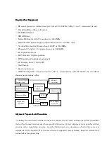


Required Test Equipment
Required Test Equipment
Required Test Equipment
Required Test Equipment
□
□
□
RF signal generator: calibrated output level at
1000 MHz (0 dBµ =1.0 µV - terminated circuit)
□
□
□
Deviation Meter (linear detector)
□
□
□
AF Millivoltmeter
□
□
□
SINAD Meter
□
□
□
Inline Wattmeter with 5% accuracy at
1000
MHz
□
□
□
Regulated DC Power Supply: adjustable from 10 to 17 VDC, 30A
□
□
□
50-ohm Non-reactive Dummy Load: 200W at
1000
MHz
□
□
□
Frequency Counter: >0.1 ppm accuracy at
1000
MHz
□
□
□
AF Signal Generator
□
□
□
DC Voltmeter: high impedance
□
□
□
RF Sampling Coupler
(attenuation pad)
□
□
□
AF Dummy Load: 4 ohm, 20W
□
□
□
Oscilloscope
□
□
□
Spectrum Analyzer
□
□
□
IBM PC/compatible computer w/Vertex CT-71 programming cable(CT-29+CT-70) and CE-35
channel programming editor.
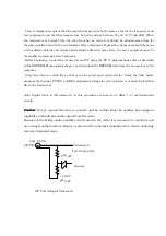
50-
Ω
RF Signal
Dummy load Generator
RF Sampling
Inline Wattmater Coupler
Transceiver
Deviation Meter CT-70
CT-29 Connection
Frequeuncy Cable Power Supply
Counter IBM PC 13.8V DC
COM port
Alignment Preparation & Precautions
Alignment Preparation & Precautions
Alignment Preparation & Precautions
Alignment Preparation & Precautions
A dummy load and inline wattmeter must be connected to the main antenna jack in all procedures
that call for transmission, except where specified otherwise. Correct alignment is not possible with an
antenna. After completing one step, read the following step to determine whether the same test
equipment will be required. If not, remove the test equipment (except dummy load and wattmeter, if
connected) before proceeding.