


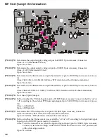


10
The output of the VCO is amplified by the
Q1020
and rout-
ed to the pin 5 of the PLL IC. Also the output of the VCO
is amplified by the
Q1021
and routed first local/Power
Module according to
D1022
.
The PLL IC consists of a prescaler, fractional divider, ref-
erence divider and phase comparator and charge pump.
This PLL IC is fractional-N type synthesizer and performs
in the 40 or 50 kHz reference signal, which is eighth of the
channel step (5 or 6.25 kHz). The input signal from pin 5
and 8 of the PLL IC is divided down to the 20 kHz and
compared at phase comparator. The pulsed output signal
of the phase comparator is applied to the charge pump
and transformed into DC signal in the loop filter. The DC
signal is applied to the VCO and locked to keep the VCO
frequency constant.
PLL data is output from "DCS_E" (pin100), "CLOCK"
(pin2) and "PLL_E" (pin98) of the microprocessor
Q2013
.
The data are input to PLL IC when the channel is changed
or when transmission is changed to reception and vice
versa. A PLL lock condition is always monitored by the
pin20 of the
Q2013
. When the PLL is unlocked, the UL
goes low.
6. Miscellaneous Circuits
6-1 DCS/LTR Demodulator
DCS signals are demodulated on the PANEL-UNIT, It is
demodulated by
Q2116
(
AK2345
), amplifier
Q2015
, and
comparator
Q2021
.
6-2 CTCSS encoder/decoder
The CTCSS code is generation and encoding by CTCSS
encoder/decoder IC
Q2016
(
AK2345
).
6-3 MPU
Operation is controlled by 8-bit MPU IC
Q2013
(
LC87F72C8A
). The system clock uses a 3.6864MHz crys-
tal for a time base. IC
Q2003
(
S-80735SN
) resets the MPU
when the power is on, and monitors the voltage of the
regulated 5V power supply line.
6-4 DCS/LTR Encorder
The DCS code is generation and encoding by MPU IC
Q2013
(
LC87F72C8A
). It is filtered by
Q2021
(
NJM2902V
)
and adjusted the level by
Q2014
(
M62364FP
).
6-5 Compandor
The Compandor is active when Pin90 of
Q2013
(
LC87F72C8A
) is “High”. When the Compandor is ac-
tive, MIC Audio is compressed, and detected audio is ex-
panded by
Q2017
(
LA8630M
).
7. Power Supply Circuits
7-1 All 13.8V
13.8V is always supplied to Power AMP
Q1014
(
RA30H4452M
). Switched 13.8V is supplied to AF Power
AMP
Q1509
(
TDA2003H
) and 9V Regulator
Q1004
(
MM1216EN
) and
Q1005
(
2SB1201STP
).
7-2 All 9V
9V regulated from 13.8V by
Q1004
(
MM1216EN
) and
Q1005
(
2SB1201STP
).
7-3 VCO 9V
9V is filtered by Ripple Filter and is supplied to VCO Os-
cillator
Q1013
(
2SK508-K52
),
Q1015
(
2SC5107-O
), and
VCO BUFFER AMP
Q1015
(
2SC5107-O
).
7-4 5V (RF-UNIT)
5V in RF-UNIT is regulated by REGULATOR IC
Q1024
(
NJM78L05UA
). 5V is supplied to PLL IC
Q1023
(
SA7025DK
), FM IC
Q1028
(
TA31136FN
), and Reference
Oscillator
Q1027
(
23C4116GR
).
7-5 TX 9V
TX 9V is active on transmit. TX 9V is supplied to ANT SW
D1005
,
D1007
(
UM9957F
) and TX DRIVER
Q1022
(
2SC5415E
),
Q1025
(
2SC5107-O
).
7-6 RX 9V
RX 9V is active on receive. RX 9V is supplied to RX RF
AMP
Q1026
(
3SK228
) and MIXER
Q1011
(
2SC4227-R34
).
7-7 5V (RF-UNIT)
9V from RF-UNIT is regulated to 5V by REGULATOR IC
Q2006
(
NJM78L05UA
) in PANEL-UNIT.
Circuit Description
Summary of Contents for VX-2500V
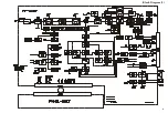
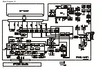
Page 5: ...5 Block Diagram 1 ...
Page 6: ...6 Block Diagram 2 ...
Page 7: ...7 Interconnection Diagram ...
Page 8: ...8 Note ...
Page 32: ...PANEL Unit 32 Note ...


