


24
Transmitter Alignment
MIC Gain Alignment
r
Connect the AF millivoltmeter to
TP1003
on the MAIN Unit.
r
Connect the AF Generator to the
MIC IN
jack on the MIC
Adapter Unit.
r
Select the “
TX IF
” channel (10.25000 MHz, USB).
r
Inject a signal from the AF Generator to 1500 Hz, then adjust
the AF Generator output level for 8 mV.
r
Key the transmitter, adjust
VR1001
on the MAIN Unit for
30 mV ± 3 mV on the AF millivoltmeter.
TX IF Coils Alignment
r
Remove the coaxial plug from
J1004
on the MAIN Unit,
then connect the RF millivoltmeter and 50
W
resistor to
J1004
.
r
Connect the AF Generator to the
MIC IN
jack on the MIC
Adapter Unit.
r
Select the “
TX IF
” channel (10.25000 MHz, USB).
r
Inject a signal from the AF Generator to 1500 Hz, then adjust
the AF Generator output level so that the RF millivoltmeter
reading is approximately 0 dBm.
r
Key the transmitter, adjust
T1010
,
T1018
,
T1019
,
T1020
,
and
T1022
on the MAIN Unit in succession several times
for maximum indication on the RF millivoltmeter.
r
Disconnect the RF millivoltmeter and 50
W
resistor, then re-
place the plug into
J1004
.
Carrier Balance Pre-Alignment
r
Remove the coaxial plug from
J1004
on the MAIN Unit,
then connect the RF millivoltmeter and 50
W
resistor to
J1004
.
r
Select the “
TX IF
” channel (10.25000 MHz, USB).
r
Key the transmitter with no microphone input, adjust
TC1002
and
VR1003
on the MAIN Unit for minimum indication on
the RF millivoltmeter.
r
Disconnect the RF millivoltmeter and 50
W
resistor, then re-
place the plug into
J1004
.
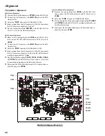
Alignment
MAIN Unit Alignment Points [1]
T1018
T1022
T1020
T1019
T1010
J1004
TP1003
TC1002
VR1003
VR1001
Summary of Contents for VX-1210
Page 16: ...16 Note ...
Page 17: ...17 Block Diagram ...
Page 18: ...18 Interconnection Diagram ...
Page 28: ...28 Alignment Note ...
Page 29: ...MAIN Unit 29 Circuit Diagram ...
Page 30: ...30 MAIN Unit Note ...
Page 44: ...44 Main Unit Note ...
Page 45: ...CNTL Unit 45 Circuit Diagram ...
Page 46: ...46 CNTL Unit Note ...
Page 56: ...56 CNTL Unit Note ...
Page 57: ...57 PA Unit Circuit Diagram ...
Page 58: ...58 PA Unit Note ...
Page 65: ...65 Display Unit Circuit Diagram ...
Page 70: ...70 Note ...
Page 71: ...71 Tuner Unit ATU 1210 Option Circuit Diagram ...