


2
—
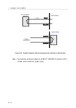
Operating and Maintaining the RU
30 / 44
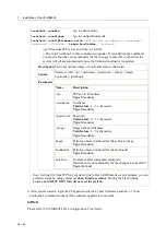
SYS
Amber
At power on phase
Red
Self-test fail
Green
Normal Operation
Green - Blink
Remote download in operation
ALM
Off
At power on phase
Red
Red
–
Blink
Major alarm set
Major and Minor alarm set
Amber
Minor alarm set
Green
Normal operation
DSL Status
Green - Scan
Green - On
Off
Green
–
Fast Blink
Green
–
Slow Blink
At power on phase
Port is activated, and linked
Disabled
Diagnostic, training
Hand-shaking
Interface
Description
HK/ALM
RJ-50 port for housekeeping inputs and one alarm contact output.
GBE1
Gigabit Ethernet trunk port 1 including an electrical (RJ-45) and an optical (SFP)
interface
GBE2
Gigabit Ethernet trunk port 2 including an electrical (RJ-45) and an optical (SFP)
interface
MGMT
Ethernet Port connected to LAN for providing system out-band EMS/Telnet
control interface, such as system monitor, control or software upgrade.
CID
RS-232 port connected to the terminal for monitoring and controlling the system.
LINE
RJ-21 connector (50-pin dual row header) for connecting DSL lines.
Button
Description
RST
An embedded hardware button for hardware resetting.
ACO
For Alarm Cut Off service.