


1
—
Installation of the VX-MD4024
9 / 44
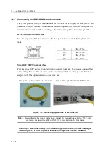
Warning
—
Ensure that all power sources to the chassis (power distribution panel) are turned off
during the connection.
Note
—
It is recommended that the -48VDC power be supplied directly and independently by a
power feeding system and also avoid having a parallel or mutual connection with other
-48VDC power supplier of telecom equipment. This is to guarantee our products against
interferences by other equipment while they are working.
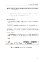
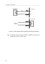
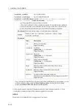
Ground Connections
This section provides the grounding rule for the VX-MD4024 . All remote system sites must be
properly grounded for optimum system performance.
In Central Office
:
There should be a CO GND that is adequately grounded. If the measured resistance from the
grounding screw (on the front panel of the DSLAM, refer to Figure 1-9) to CO GND is less than 5
Ohm, then it can be assumed that the system is well grounded. If the measured resistance is larger
than 5 Ohm, it is recommended to connect the grounding screw to CO GND using #14 or #12 AWG
wire gauge conductor.
In Remote Cabinet
:
The VX-MD4024 should be grounded by connecting a #14 or #12 AWG conductor between the
grounding screw (on the front panel of the DSLAM, refer to Figure 1-9) and the earth ground or
main grounding bar. The resistance between the chassis and the grounding bar should be less than
25 Ohm.
Figure 1-9 VX-MD4024 grounding screw on the front panel