background image

5

Vermont Castings  •  Montpelier Medium Insert Installation & Operating Manual_R26  •  05/19

3-90-30004403

SAFETY NOTICE: IF YOUR MONTPELIER MEDIUM 

INSERT IS NOT PROPERLY INSTALLED,  A HOUSE FIRE 

MAY RESULT.  TO REDUCE THE RISK OF FIRE, FOLLOW 

THE INSTALLATION INSTRUCTIONS.  CONTACT LOCAL 

BUILDING OR FIRE OFFICIALS ABOUT RESTRICTIONS 

AND INSTALLATION INSPECTION REQUIREMENTS IN 

YOUR AREA.
Requirements for Existing Fireplaces

The Montpelier Medium Insert is listed for installation within 

a properly built masonry fireplace.
The fireplace and chimney must be clean and structurally 

sound.  Have  them  inspected  by  a  qualified  professional 

chimney  sweep,  a  mason,  or  your  Vermont  Castings’ 

Authorized Dealer before the Montpelier Medium Insert is 

installed. Any deterioration (cracks, loose mortar or loose 

bricks) must be repaired.
Codes may permit removal of the damper in order to make 

a  positive  vent  connection  between  the  firebox  and  the 

chimney. However, the fireplace should not be modified in any 

way without first checking with your local building inspector or 

fire marshal. Provision should be made to restore the fireplace 

to its original condition if the insert is removed. Do not remove 

bricks or mortar that may jeopardize the compliance of the 

fireplace with local building codes.

The Montpelier Medium Insert is not listed for installation 

in factory-built fireplaces.


Requirements for Existing Chimneys

Chimney  requirements  differ  for  the  U.S.  and  Canada.  

Specifications for each are listed below. Connect the insert 

to  the  chimney  in  accordance  with  local  codes  and  the 

requirements of the listing agency as specified in this manual.

Chimney Height / U.S. and Canada

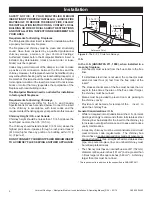
Chimney height should be no less than 15’ (4.5 m) above the 

hearth and no more than 35’ (10.5 m).
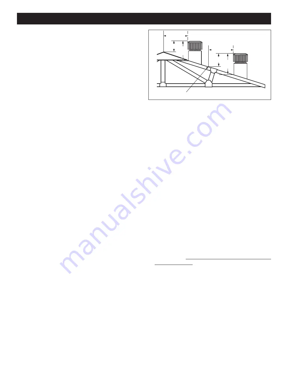
The chimney should extend at least 3’ (914 mm) above the 

highest point where it passes through a roof, and at least 2’ 

(610 mm) higher than any portion of a building within 10’ (3 

m). (Figure 2)

DO NOT CONNECT YOUR MONTPELIER MEDIUM INSERT  

TO A CHIMNEY FLUE SERVING ANOTHER APPLIANCE.

Installation

U.S. 
In the U.S. (ANSI/NFPA 211, 1988), when installed in a 

masonry fireplace:

•  A connector must extend from the flue collar to the flue 

liner.

•  If a stainless steel liner is not used, the connector must 

extend  at  least  four  (4)  feet  from  the  flue  collar  of  the 

insert.*

•  The cross sectional area of the flue must be less than or 

equal to three times the area of the flue collar.If larger, 

the chimney must be re-lined.

•  Means must be provided to prevent room air  passing to 

the chimney cavity.

•  Provision must be made for removal of the   insert  to 

clean the chimney flue.

General Considerations / U.S.

•  While not required in most jurisdictions in the U.S., Vermont 

Castings strongly recommends that a full stainless steel 

chimney liner be installed for the insert to the chimney top 

to increase overall performance and to ease and reduce 

yearly maintenance.

•  A masonry chimney must be well-constructed and must 

meet  minimum  code  requirements.    The  chimney  flue 

should have a code-approved liner made of masonry or 

pre-cast refractory tiles, straight or flexible stainless steel 

pipe, or a poured-in-place liner. An unlined chimney must 

be relined professionally.

•  The chimney must have a nominal flue size of 6" (152 mm) 

diameter or 28 square inches (181 cm

2

) but no greater than 

3 times larger or 85 square inches (548 cm

2

).  A chimney 

larger than this must be re-lined. 

2' Min.

2' Min.

3'

Min.

0 To 10'

3'

Min.

0 To 10'

AC617

RLTSKC8

2/11/98

Reference Point

Figure 2

 - The 2’-3’-10’ rule for chimneys.

* This requirement is in addition to those specified in ANSI/NFPA211.

Summary of Contents for Montpelier Medium Insert

Page 1: ...se read this entire manual before installation and use of this wood burning room heater Failure to follow these instructions could result in property damage bodily injury or even death Do not store or use gasoline or other flammable vapors and liquids in the vicinity of this or any other appliance Do not overfire If any external part starts to glow you are overfiring Close air controls Overfiring ...

Page 2: ...ging from 10 100 to 27 550 BTU hr For more complete details on stove performance and specifications please refer to Page 3 The Montpelier Medium Insert is designed tested and listed for burning wood Do not burn other fuels Installation or service of the Montpelier Medium Insert should be performed only by a qualified installer preferably NFI or WETT Canada certified Please read entire manual befor...

Page 3: ... proper operation It is against federal regulations to operate this wood heater in a manner inconsistent with operating instructions in this manual MODEL Montpelier Medium Insert LABORATORY OMNI Test Laboratories Inc REPORT NO 259 S 13 2 TYPE Solid Fuel Room Heater Wood Burning Type STANDARD s UL 1482 1996 ULC S628 93 ELECTRICAL RATING 115 VAC 60 Hz Area Heated 1 000 2 300 Square feet Loading Fron...

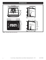
Page 4: ...0004403 Figure 1 Montpelier Medium Insert dimensions Dimensions 17 1 4 434 mm 21 1 2 548 mm 30 1 2 774 mm 28 3 4 730 mm 22 1 4 565 mm 22 1 4 564 mm 11 1 2 292 mm 4403 Montpelier dims 1 08 26 3 4 680 mm 14 1 4 362 mm 21 9 16 547 mm 21 9 16 547 mm With 3 Projection Kit Without 3 Projection Kit ...

Page 5: ...ight should be no less than 15 4 5 m above the hearth and no more than 35 10 5 m The chimney should extend at least 3 914 mm above the highest point where it passes through a roof and at least 2 610 mm higher than any portion of a building within 10 3 m Figure 2 DO NOT CONNECTYOUR MONTPELIER MEDIUM INSERT TO A CHIMNEY FLUE SERVING ANOTHER APPLIANCE Installation U S In the U S ANSI NFPA 211 1988 wh...

Page 6: ...ess than 3 times larger than the flue collar For example a chimney on an outside wall may not heat up enough to sustain an adequate draft Such a flue can often be improved if it is relined to reduce its size and or insulated to keep it warmer A positive flue connection must be made between the Insert and the first masonry tile or prefabricated metal chimney section A positive flue connection consi...

Page 7: ...d combustible Unless the fireplace and hearth are constructed over a completely non combustible surface such as unpainted concrete over dirt a thermal floor protector must be used in front of and to the sides of the door as protection against spilled coals and embers and heat radiated from the front of the insert Floor protectors must extend at least 8 203 mm from the side of the insert making the...

Page 8: ... Rbrick Rmineralboard 0 8 0 431 1 66 Step c Compare proposed system Rtotal of 1 66 to specified R of 1 49 Since proposed system Rtotal is greater than required the system is acceptable Definitions R x T x 1 25 1 49 1 k 1 0 84 1 0 29 r ft2 hr F Btu in 1 k Btu ft ft2 hr F K k K x 12 Btu in ft2 hr F R ft2 hr F Btu includes some form of thermal designation such as R value thermal resistance or k facto...

Page 9: ...be easiest to install the connector or stainless steel flue liner in the chimney first Refer to Figure 6 for the components of the venting system Carefully remove the fiber baffle by first removing the front air tube If necessary removing the remaining air tubes will allow easier access Remove the iron flue collar from the stove and fasten either the adapter pipe or flue liner to it by drilling th...

Page 10: ...en will be in the home In the event of a stove pipe or chimney fire Evacuate the house immediately Notify the fire department If the fire isn t too threatening closing down the insert tight damper primary air all doors will help to smother the fire Inspect your insert stove pipe and chimney for any damage caused by the fire and correct any damage before using your insert again 8 Connect the Flue C...

Page 11: ...g on wood species and fuel load The fan speed should be set at low fully closed when operating at low to medium burn rates and may be set anywhere between low and high when operating at high burn rates Refer to Figure 10 for fan access The Montpelier Medium Insert s air supply is increased when the control lever is moved to the left and decreased when moved to the right It may be set anywhere betw...

Page 12: ...ir controls You will quickly find that a specific setting will give you a fixed amount of heat It may take a week or two to determine the amount of heat and the length of burn you should expect from various settings Most installations do not require a large amount of combustion air especially if adequate draft is available Do not for any reason attempt to increase the firing of your heater by alte...

Page 13: ...y adjust the air control and fan speed for your desired heat level Followtheseguidelinesasyoustartandmaintainthefire and remove the ashes Prior to starting a fire with a cold stove it is recommended to clear the lower primary air holes located under the front brick To do this remove the andiron and lift out the front refractory brick Sweep any ash accumulation out of the three 3 air slots Keeping ...

Page 14: ...lace always remove and dispose of the ash properly NOTE If the charcoal bed is relatively thick and your fuel is well seasoned it is possible to add fresh fuel smaller pieces first close the door and reset the air control immediately Special Tactics for Cold Climate Heating The Montpelier Medium Insert is capable of producing up to 40 000 Btu hour and heating an area of up to 1 500 sq ft However m...

Page 15: ...dically to prevent etching To clean the glass use the following procedure Be sure the glass is completely cool Cleaning with water will work in most cases Use a glass cleaner especially made for this purpose only if deposits are specially heavy If heavy deposits are a frequent occurrence however evaluate your operating techniques Do not use abrasive cleaners Rinse the glass thoroughly Dry the glas...

Page 16: ...kets Your Montpelier Medium Insert uses rope type fiberglass gaskets to make a tight seal between some parts With use particularly on those parts that move gaskets can become brittle and compressed and can begin to lose their effectiveness These will need periodic replacement All of the gaskets used are made of fiberglass The three sizes of replaceable gasket are listed below along with their appl...

Page 17: ...placing glass which start on Page 15 Replace gaskets Follow steps 1 4 above Replace the glass Replace the door The Chimney System A Clean Chimney System is Safer and Works Better Although the non catalytic combustion system in your Montpelier Medium Insert can reduce creosote formation dramatically it is not a substitute for regular inspection and cleaning of the chimney and chimney connector Lear...

Page 18: ... the system if necessary Yearly Spring Cleaning Disassemble the flue connection and take it outdoors for inspection and cleaning Replace weak sections of connector Inspect the chimney for signs of deterioration Repairs to a masonry chimney should be made by a professional mason Replace damaged sections of prefabricated chimney Your local Vermont Castings dealer or a chimney sweep can help determin...

Page 19: ...n Bottom Low 30004335 3 Brick Bottom Low 30004327 4a Brick Bottom Slanted Right 30006706 4b Brick Bottom Slanted Left 30006707 5 Brick Back 30004326 6 Brick Bottom Up 30004329 7 Brick Right End 30004330 8 Brick Left End 30004331 9 Insulation End Int 30004334 10 End Right 30004308 11 End Left 30004309 12 Back 30004307 13 Andiron 30004321 Ref Description Part Number 14 Tube A Secondary Air Tube 3000...

Page 20: ...Wire Assy 30004407 Power Cord 1601782 Snapstat 30005236 Snapstat Bracket 30005538 D Knob 1604419 33 Ashlip Refer to Enamel Parts Chart 34 Bottom Assembly 30004797 35 Cover Power Cord 30004379 36 Shroud Outer 30004392 37 Shroud Top SRV30004614 38 Flue Collar 30004317 39 Flange Right Side Surround 30004381 Ref Description Part Number 40 Flange Left Side Surround 30004380 41 Clip Glass 30001715 42 Gl...

Page 21: ...irst occupancy of the dwelling or six months after the sale of the product by an independent authorized HHT dealer distributor whichever occurs earlier However the warranty shall commence no later than 24 months following the date of product shipment from HHT regardless of the installation or occupancy date The warranty period for parts and labor for covered components is produced in the following...

Page 22: ...ting appliance some changes in color of interior and exterior surface finishes may occur This is not a flaw and is not covered under warranty Damage to printed plated or enameled surfaces caused by fingerprints accidents misuse scratches melted items or other external sources and residues left on the plated surfaces from the use of abrasive cleaners or polishes Repair or replacement of parts that ...

Page 23: ... result of but not limited to improper chimney or venting installation LIMITATIONS OF LIABILITY The owner s exclusive remedy and HHT s sole obligation under this warranty under any other warranty express or implied or in contract tort or otherwise shall be limited to replacement repair or refund as specified above In no event will HHT be liable for any incidental or consequential damages caused by...

Page 24: ...24 Vermont Castings Montpelier Medium Insert Installation Operating Manual_R26 05 19 3 90 30004403 352 Mountain House Road Halifax PA 17032 www vermontcastings com ...

Reviews: