background image

Vermont Castings  •  Encore Model 2040-CAT-C Installation Manual_R3  •  2019 - ___ •  09/20

19

8390-204i

J. Installing/Removing Catalyst

1.  Remove the access cover by gently lifting up and pulling 

out from the bottom edge, Figure 5.9.

2.  Remove the inner cover by pulling it straight out, Figure 

5.10.

3.  Remove  the  catalyst  by  gently  pulling  it  straight  out, 

Figure 5.11. Place the catalyst where the catalyst’s 

ceramic components will not be damaged.

ST1187

remove access cover

Access 

Cover

Figure 5.9

 - Remove access cover.

ST1188
remove inner cover 

Inner Cover

Figure 5.10

 - Remove inner cover.

ST1189
remove catalyst

Remove Catalyst

Figure 5.11

 - Remove catalyst.

K. Outside Air Kit Installation 

A source of air (oxygen) is necessary in order for combustion 

to take place. Whatever combustion air is consumed by the 

fire must be replaced. Air is replaced via air leakage around 

windows and under doors. In homes that have tightly sealed 

doors and windows, an outside air source is needed. An 

optional Outside Air Kit is avail

able. 

Items Needed for Installation (not supplied)

•  Phillips head screw driver

•  Outside air shield

•  Wire ties

•  Plastic outside air vent

•  Flex / Rigid pipe

•  Silicone sealant

•  Drills and saws necessary for cutting holes through 

the wall or flooring in your home.

1.  Remove all materials from packing box.
2.  Using a #2 Phillips screw driver attach the flex adapter to 

the appliance using 4 screws. Figure 5.12 & 5.13.

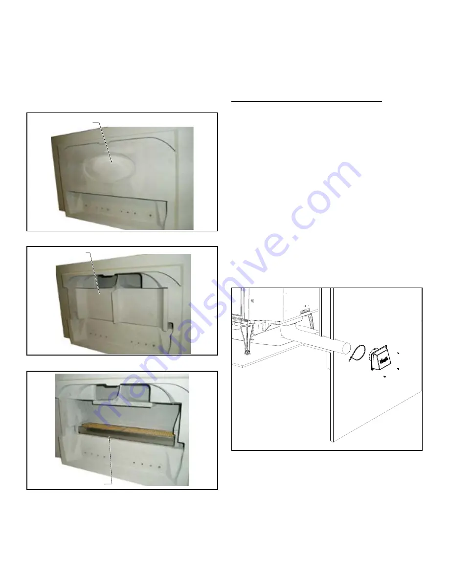
3.  Floor & Rear Installation: Cut a 3” (76 mm) hole in outside 

wall or floor to accommodate outside air piping. Use 3” 

(76 mm) aluminum metal flex or rigid piping to directly 

connect outside air to appliance intake. Use the supplied 

termination cap with a rodent screen. Seal between the 

wall (or floor) and the pipe with silicone to prevent moisture 

penetration. 

Figure 5.12

 - Rear Installation

Summary of Contents for Encore 2044-CAT-C

Page 1: ...ce Do not over fire If appliance or chimney connector glows you are over firing Over firing will void your warranty Comply with all minimum clearances to combustibles as specified Failure to comply may cause house fire Installation and service of this appliance should be performed by qualified personnel Hearth Home Technologies recommends HHT Factory Trained or NFI certified professionals HOT SURF...

Page 2: ... and Installation Considerations 5 B Fire Safety 5 C Negative Pressure 5 D Tools And Supplies Needed 6 E Inspect Appliance and Components 6 F Install Checklist 7 3 Dimensions and Clearances A Appliance Dimensions 8 B Hearth Protection Requirements 9 C Clearances to Combustibles 10 D Locating Your Appliance Chimney 11 E Chimney Termination Requirements 11 F Chimney Location 2 10 3 Rule 12 4 Chimney...

Page 3: ...it must be bolted to the floor This can be done using an appropriate fastener for the application The appliance must be properly grounded to the frame of the mobile home with 8 copper ground wire and chimney must be listed to UL103 HT or a listed UL 1777 full length six 152mm diameter liner must be used Mobile Home Bracket Kit 0003264 must be installed in a mobile home installation D Glass Specifi...

Page 4: ... or surfaced with any of the following materials Wood Compressed Paper Plant Fibers Plastic Plywood OSB Sheet Rock drywall Any material that can ignite and burn flame proofed or not plastered or non plastered NOTE This installation must conform with local codes In the absence of local codes you must comply with the UL1482 11 UL 737 11 UM 84 HUD and NPFA211 in the U S A and the ULC S627 00 and CAN ...

Page 5: ...ing should be given serious consideration 1 Install at least one smoke detector on each floor of your home to ensure your safety They should be located away from the heating appliance and close to the sleeping areas Follow the smoke detector manufacturer s placement and installation instructions and be sure to maintain regularly 2 2 Getting Started Check building codes prior to installation Instal...

Page 6: ...ed duct work and air handler joints and seams taped or sealed Basement installations should be avoided Reciprocating saw Framing material Pliers High temp caulking material Hammer Gloves Phillips screwdriver Framing square Flat blade screwdriver Electric drill and bits Plumb line Safety glasses Level Tape measure Misc screws and nails 1 2 3 4 in length 6 or 8 self drilling screws Installation and ...

Page 7: ...ocked and secured in place with proper clearance Chimney meets recommended height requirements 16 Feet Roof flashing installed and sealed Terminations installed and sealed Clearances Combustible materials not installed on non combustible areas Verified all clearances meet installation manual requirements Mantels and wall projections comply with installation manual requirements Protective hearth st...

Page 8: ...65 mm 15 1 2 394 mm 5 127 mm 2 7 8 73 mm 23 3 4 603 mm 15 381 mm Door opening width 19 7 8 505 mm Figure 3 3 Top View 5295 Encore 2N1 dimensions 1 3 4 44 mm 3 3 4 95 mm 16 7 8 429 mm 25 635 mm Top exit flue collar height 27 686 mm 25 3 4 654 mm 18 1 2 470 mm 7 1 4 184 mm 27 686 mm 22 3 4 578 mm Flue Centerline to glass surface Door opening width 19 7 8 505 mm Figure 3 2 Side View 5295 Encore 2N1 d...

Page 9: ...ctions must extend beneath the flue pipe when installed with horizontal venting and extend 2 51 mm beyond each side Figure 3 7 39 1 4 in minimum 44 in minimum 16 in FRONT DOOR OPENING 6 in USA 6 in Figure 3 5 Fire Risk Hearth pads must be installed exactly as specified High temperatures or hot embers may ignite concealed combustibles WARNING Figure 3 6 67 1 2 in 40 in 22 in 55 1 2 in 16 in front d...

Page 10: ...9 1 2 Fire Risk Comply with all minimum clearances to combustibles as specified Failure to comply may cause house fire WARNING 21 533 mm Mantel 12 Max 53 1346 mm Horizontal Through Wall Top and Side View D B C G H Appliance to Ceiling Clearance Figure 3 10 Fireplace and Mantel Trim Clearances Unprotected NFPA 211 Protected A Mantel Trim 28 711 mm 15 381 mm B Top Trim 25 635 mm 15 381 mm C Side Tri...

Page 11: ...e chimney should Install through the warm space enclosed by the building envelope This helps to produce more draft especially during lighting and die down of the fire Penetrate the highest part of the roof This minimizes the affects of wind turbulence and down drafts NOTICE Locating the appliance in a basement or in a location of considerable air movement can cause intermittent smoke spillage from...

Page 12: ...ing the diameter of the chimney can affect draft and cause poor performance It is not recommended to use offsets and elbows at altitudes above 4000 feet above sea level and or when there are other factors that affect flue draft 3 ft 91 cm Minimum Less than 10 ft 305 cm 2 ft 61 cm 3 ft 91 cm Minimum 10 ft 305 cm To Nearest Roofline 2 ft 61 cm Pitched Roof Figure 3 13 10 ft 305 cm or more 3 ft 91 cm...

Page 13: ...rformance of the stove suffers Imagine a vacuum cleaner with a hole in the hose to understand the effecthere Insomecasestheotherappliance canevencause a negative draft through the stove and result in a dangerous draft reversal Chimney Height The common wisdom tells us that a taller flue draws better than a short one A rule of thumb for minimum height states that the total system height from the fl...

Page 14: ...neys Chimney The chimney can be new or existing masonry or prefabricated and must meet the following minimum requirements specified in Section 4C C Chimney Systems Prefabricated Metal Chimney Must be minimum 6 152 mm diameter ID high temperature chimney listed to UL 103 HT 2100 F or ULC S629M Must use components required by the manufacturer for installation Must maintain clearances required by the...

Page 15: ...ng lumber to fit into wall opening Inside opening of frame should be no less than 14 x 14 356 mm x 356 mm Figure 4 4 Attach the wall spacer to the chimney side of the frame 5 Nail the frame into the wall opening The spacer should be on the chimney side 6 Insert the section of the solid insulated chimney into the outer wall of the masonry chimney 7 Tightly secure the length of the solid insulated c...

Page 16: ... be 6 152mm UL103 HT WARNING WARNING Asphyxiation Risk DO NOT CONNECT THIS Appliance TO A CHIMNEY FLUE SERVICING ANOTHER APPLIANCE DO NOT CONNECT TO ANY AIR DISTRIBUTION DUCT OR SYSTEM May allow flue gases to enter the house Improper installation adjustment alteration service or maintenance can cause injury or property damage Refer to the owner s information manual provided with this appliance For...

Page 17: ... get hot Store the handle in the handle holder installed behind the right front leg Figure 5 4 CAUTION Overtightening can strip tapped threads Figure 5 1 Remove unit from shipping brackets 1 4 20 Bolt A Setting up your Stove Remove the unit from the shipping brackets by removing 2 1 4 20 hex head bolts from each shipping bracket leaving brackets attached to the skid Figure 5 1 Save the 1 4 20 hex ...

Page 18: ...he adjustment E Reverse Flue Collar If necessary Remove the 4 sheet metal screws that hold the flue collar heat shield in place Once heat shield is removed remove the 2 screws that attach the flue collar to the back of the stove Figure 5 6 Be sure the gasket around the flue collar opening is in position when you screw the collar back onto the stove Figure 5 7 1 4 1 8 Bracket mounting screw hole lo...

Page 19: ...the fire must be replaced Air is replaced via air leakage around windows and under doors In homes that have tightly sealed doors and windows an outside air source is needed An optional Outside Air Kit is available Items Needed for Installation not supplied Phillips head screw driver Outside air shield Wire ties Plastic outside air vent Flex Rigid pipe Silicone sealant Drills and saws necessary for...

Page 20: ... CO detector manufactures placement and installation instructions and maintain regularly You may not however wish to install a detector in the immediate vicinity of the stove Depending on the sensitivity of the unit the alarm can be set off while you are tending the fire or emptying the ashes If you install a detector in the same room locate it as far away from the stove as possible Safety Tips Co...

Page 21: ...he serial number label on the back of the stove for clearances to combustibles 6 Floor protection requirements must be followed precisely Refer to the Floor Protection section in this manual 7 In Canada this appliance must be connected to a 6 inch 152 mm factory built chimney conforming to CAN ULC 629M STANDARD FOR FACTORY BUILT CHIMNEYS Refer to the Floor Protection section in this manual 8 Use s...

Page 22: ... Important operating and maintenance instructions included Leave this manual with party responsible for use and operation Read understand and followtheseinstructions for safe installation and operation DO NOT DISCARD This product may be covered by one or more of the following patents United States 5341794 5263471 6688302 7216645 7047962 or other U S and foreign patents pending We recommend that yo...

Reviews: