


7
User Guide DSR-3 - dual spring reverb
EN
Controls and Connections
Front Panel
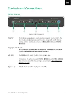
Figure 1: DSR-3 front panel
q
INPUT
This high impedance input is used to feed audio signals into the DSR-3. The
front input overrules the rear panel TS- and XLR-inputs
k
and
j
. It is rou-
ted in parallel to reverberation channels
SPRING REVERB A and SPRING
REVERB B.
w
spring reverb channels
Both channels
SPRING REVERB A and SPRING REVERB B are described in
chapter „Spring Reverb Channels A and B“ on page 9.
e
MODE
The
MODE
switch selects the DSR-3's operating modes.
It determines if and how channels
SPRING REVERB A and SPRING REVERB
B are interconnected. The three settings are described in „DSR-3 Operating
Modes“ on page 12.
r
pilot lamp
With the DSR-3 switched on, the pilot lamp is lit.
Summary of Contents for DSR-3
Page 1: ...Bedienungsanleitung User Guide DSR 3...
Page 17: ...16...


