background image

Control elements and connections

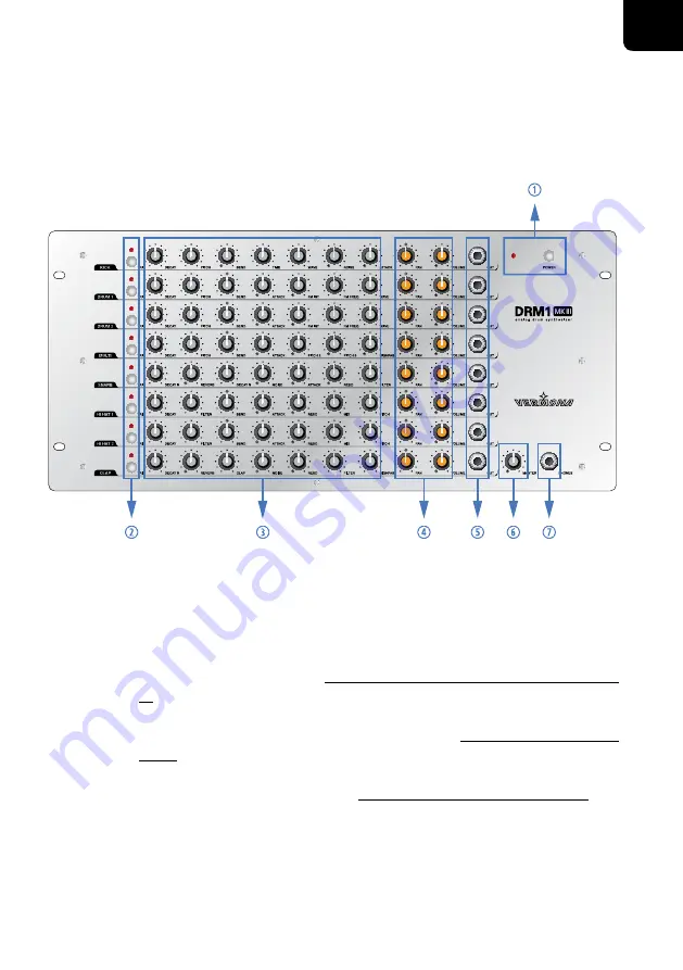
Front Panel/User Interface 

Figure 1: User Interface of the DRM1 MKIII


POWER

 - power switch with LED


TRIG

 button with LED - triggers sound in instrument channel


sound shaping parameters (see "The DRM1 MKIII’s instrument channels" on page 
10)


PAN

 and 

VOLUME

 - channel volume and panning (see "The Sound Generation" on 

page 9)


OUT

 - individual outputs/inserts (see "Individual Outputs/Inserts" on page 20)


MASTER

 - overall volume


PHONES

 - headphones output

7

User Guide DRM1 MKIII

EN

Summary of Contents for DRM1 MKIII

Page 1: ...Bedienungsanleitung User Guide DRM1 MKIII...

Page 2: ...ck due to significant historical and political changes This product was introduced many years ago but the DRM1 is still being produced Why There are still musicians that do not own this product Becaus...

Page 3: ...Rear Panel 8 The Sound Generation 9 KICK 10 DRUM 1 DRUM 2 12 MULTI 13 SNARE 14 HI HAT 1 HI HAT 2 15 CLAP 17 MIDI Functions 18 Setting the MIDI channel and note number for an individual instrument cha...

Page 4: ...t consult an electrician for replacement of the obsolete outlet 8 Protect the power cord from being walked on or pinched particularly at plugs convenience receptacles and the point where they exit fro...

Page 5: ...tallation Ensure that the room in which you use the DRM1 MKIII is wired in accordance with the local electrical code and checked by a qualified inspector Do not install the DRM1 MKIII in hot humid or...

Page 6: ...amplifier After connecting the module to a power socket using the supplied power chord setup the audio and MIDI connections as follows Setting up audio connections CONNECT FIRST AND THEN SWITCH ON To...

Page 7: ...to an audio interface For safety reasons while connecting and powering up the unit turn down the MASTER control of the DRM1 MKIII as well as the input controls of the units that follow in the signal c...

Page 8: ...th LED triggers sound in instrument channel sound shaping parameters see The DRM1 MKIII s instrument channels on page 10 PAN and VOLUME channel volume and panning see The Sound Generation on page 9 OU...

Page 9: ...ower connector and fuse holder The fuse holder of the power connector is equipped with an active and a replacement fuse Check the active fuse if the DRM1 MKIII shouldn t work anymore and replace it by...

Page 10: ...ous analogue drum machines invented by our friends from Japan The DRM1 MKIII has a lot to offer It covers many aspects of those classic units but also a lot more But one thing can certainly be said Th...

Page 11: ...found in genres such as Hip Hop or R n B With DECAY set to maximum long sounding bass drums can be achieved Use these for Jeep Beats D n B and Dubstep BOOOOOOOM PITCH sets the overall sound frequency...

Page 12: ...th At higher values the sound will start to overdrive and distort making an additional overdrive or distortion pedal superfluous when wanting to create harder sounding bass drums NOISE adds a short fi...

Page 13: ...AY setting ATTACK adds a short fixed needle impulse to the sound s start to support its assertiveness Always adjust ATTACK in correlation to the complete mix FM INT defines the intensity of the freque...

Page 14: ...mpulse to the sound s start to support its assertiveness Always adjust ATTACK in correlation to the complete mix PITCH 2 setsthepitch frequencyofthesecondoscillator ChangingPITCHwillalwayschange the f...

Page 15: ...s effect is only audible with NOISE being enabled NOISE sets the volume of the sound s noise component By this the snare will receive more body and therefore sounds more authentic With this control s...

Page 16: ...sets the release time or the sound s length FILTER sets the cutoff frequency of the low pass filter coloring the overall sound of the channel BEND adjusts the amount of a possible cutoff modulation by...

Page 17: ...her as cymbal open hi hat or as closed hi hat The closed hi hat has a fixed short decay time independent of the DECAY control After switching on the DRM1 MKIII the TRIG button defaults to trigger the...

Page 18: ...e speed of a sequence of the individual claps needle impulses NOISE adjusts the amount of noise that sounds conjointly with the claps Without adding any NOISE the results sound unnatural RESO specifie...

Page 19: ...these steps for each instrument channel if needed This way you may play the DRM1 MKIII s sound on different MIDI channels Setting the MIDI channel and note numbers for all instrument channels 1 Press...

Page 20: ...nd The closed hi hat is automatically assigned to a note number two semitones equals two MIDI notes below the open hi hat Therefore pay attention to keep that position unoccupied when assigning note n...

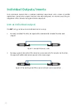
Page 21: ...n the output jack Use as individual output The OUT jack can be used as an individual out in two ways 1 By using a standard TS cable the signal will be automatically excluded from the main outputs Figu...

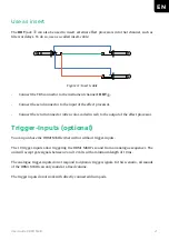
Page 22: ...n red to the output of the effect processor Trigger Inputs optional You can purchase the DRM1 MKIII either with or without trigger inputs The 10 trigger inputs allow triggering the DRM1 MKIII s sound...

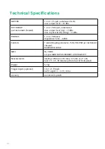
Page 23: ...g 18 dBu PHONES 1 x 1 4 TRS jack impedance 32 600 Controls 7 sound shaping parameter PAN VOLUME per instrument channel MASTER VOLUME MIDI IN THRU accepts MIDI NOTE NUMBERS with VELOCITY Measurements d...

Page 24: ...HDB electronic GmbH Badesteig 20 08258 Markneukirchen GERMANY Fon 49 0 37422 4027 0 Email info vermona com Web www vermona com...

Reviews: