Verderflex iDura 10 Supplementary Document Download Page 7

iDura 05-35

Version 1.0v-11/2020

© Verder International B.V

7 | Page

3  Transport, Storage and 

 Disposal

3.1   Transport


Always transport the pump in a stable position and ensure 

that the pump is securely attached to the pallet.

3.1.1  Unpacking and Inspection on Deliv-

ery

1.  Report any transport damage to the manufacturer/distribu-

tor immediately.

2.  Retain the pallet if any further transport is required.

3.1.2 Lifting

Death or crushing of limbs can be caused by falling 

loads!

1.  Use lifting gear appropriate for the total weight to be trans-

ported.

2.  Make sure the pump and accessories are lifted and moved 

by qualified lifting personnel equipped with suitable lifting 

gear.

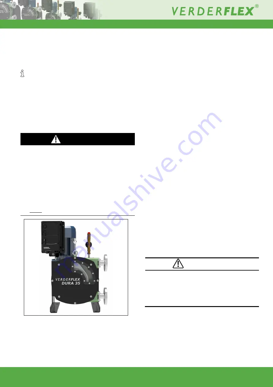
3.  Where lifting eye is available, fasten the lifting gear to the 

lifting eye as shown in the following illustration. The lifting 

eye is available for Dura 15, 25 and 35 only.

4.  Do not stand under suspended loads.

DANGER

Figure 1  Fastening Lifting Gear to Pump

3.2   Storage Conditions

1.  Make sure the storage location meets the following  

conditions:

– 

Dry, humidity not to exceed 85%, non-condensing

– 

Out of direct sunlight

– 

Frost-free; temperature range -5° to +45°C

– Vibration-free

– Dust-free

2.  Depending on these conditions, it may be advisable to 

place a moisture-absorbing product, such as Silica gel, 

inside the pump’s housing or to coat the pump’s inner 

surfaces with moisture-repelling oil, such as WD40, 

whilst the pump is stored.

3.  Hoses should be stored as supplied in their wrapper and 

should be stored away from direct sunlight, flat without 

any bends or kinks and at room temperature, with end 

caps fitted.

4.  Lubricants should be stored under normal warehouse 

conditions with their caps securely fastened.

5.  Gearboxes may require intermittent attention as indicated 

by the gearbox manufacturer’s recommendations.

3.3   Interim Storage After Using the  

   Pump

The hose should be removed from the pump. 

The pump housing lubricant should be drained.

The pump housing should be washed out, allowed to dry 

and any external build up of product removed. 

3.4   Interim Storage Before Using  

    the Pump

Pump damage caused by interim storage!

u

  Allow the pump to reach ambient temperature before 

use.

Please observe the storage recommendations and use 

by dates which apply to hose you may wish to bring into 

service after storage.

CAUTION

Summary of Contents for iDura 10

Page 1: ...Peristaltic Industrial Hose Pump Supplementary Document Version 1 0v 11 2020 Print No 01 iDura 5 7 10 15 25 35 ...

Page 2: ...ion 1 0v 11 2020 Print No 01 iDura 5 7 10 15 25 35 The information in this document is essential for the safe operation of Verderflex i Dura pumps This document must be read and understood thoroughly prior to installation of unit electrical con nection and commissioning ...

Page 3: ...lectrical Connection 4 2 Electric Shock Hazard 4 3 Connecting to the Power Supply 5 Operation supplementary 6 Maintenance 6 1 Hose Change 6 1 1 Draining Lubricant 6 1 2 Hose Change Using Inverter 6 1 3 Hose Change Manually 6 1 4 Re installing the Hose Port Flanges Lubricant Refill and Fitting the Inspection Window 7 Service and Inspection of Electrical Components 8 Troubleshooting for the iDura In...

Page 4: ...Operating Company u Keep this manual available at the operating site of the pump u Ensure that personnel read and follow the instructions in this manual and any other applicable documents especially all safety instructions and warnings u Observe any additional rules and regulations referring to the system Qualified personnel fitter u Read observe and follow this manual and the other applicable doc...

Page 5: ...cific headings Operate the pump only if it and all associated systems are in good functional condition Only use the pump and inverter as intended fully aware of safety and risk factors involved and the instructions in this manual Keep this manual and all other applicable documents complete legible and accessible to personnel at all times Refrain from any procedure or action that would pose a risk ...

Page 6: ...ted components Do not lean or step on them or use as climbing aid Do not use them to support boards ramps or beams Do not use them as a fixing point for winches or sup ports Do not de ice using gas burners or similar tools u Do not remove the safety guarding for hot cold or moving parts during operation u Reinstall the safety equipment on the pump as required by regulations after any repair mainte...

Page 7: ... 85 non condensing Out of direct sunlight Frost free temperature range 5 to 45 C Vibration free Dust free 2 Depending on these conditions it may be advisable to place a moisture absorbing product such as Silica gel inside the pump s housing or to coat the pump s inner surfaces with moisture repelling oil such as WD40 whilst the pump is stored 3 Hoses should be stored as supplied in their wrapper a...

Page 8: ...erience They must care fully read this safety information and the instructions in this Guide and follow all information regarding transport storage installation and use of the Inverter including the specified environmental limitations 3 Do not perform any flash test or voltage withstand test on the Inverter 4 In order to protect inverter and motor from high voltage or transient damage it is recomm...

Page 9: ...osi tion and that power is available to the inverter 2 Switch on the inverter using the built in isolator switch and check no errors are displayed on screen 2 3 Directional switch governs which direction the pump will turn When set to the right position the pump should turn clockwise if not refer to g 4 3 Connecting to the Power Supply 4 Speed dial allows governance over pump rotor speed be tween ...

Page 10: ...of both clamp rings where fitted 2 Set directional dial to whichever direction is preferable and the speed dial to minimum setting 3 The motor will slowly drive out the hose If at this point you are performing inspection on the rotor or pump cavity turn off inverter and lock out using an appropriate lock out tag out 4 Clean the pump housing 5 Inspect the flanges for damage and signs of wear 6 1 3 ...

Page 11: ...onfiguration 1 E TriP the hose burst sensor has been triggered Check for a hose burst 2 l_t_trP suspected motor overtemperature Allow motor to cool and restart inverter 8 1 Hose Burst Detection and Vent Kit Hose burst sensor supplied as standard with the iDura have been pre wired to the inverter No further wiring has to be done by the user to use the hose burst detection Verderflex hose burst dete...

Page 12: ...ed 1 Yes 21 Speed 2 Yes 22 Speed 3 Yes 23 Speed 4 Yes 24 2nd ramp time fast stop Yes 25 Analogue output function select Yes 26 Skip frequency hysteresis band Yes 27 Skip frequency centre point Yes 28 V F characteristic adjustment voltage No 29 V F characteristic adjustment frequency No 30 Start mode automatic restart fire mode operation Yes 31 Keypad start mode select No 32 DC injection mode and d...

Page 13: ...I controller operating mode Yes 44 PI reference source select Yes 49 PI control wake up error level No 50 User output relay hysteresis Yes 51 Motor control mode Yes 52 Motor parameter autotune Yes 53 Vector mode gain No 54 Max current limit in vector control No 55 Motor stator resistance No 56 Motor stator d axis inductance No 57 Motor stator q axis inductance No 58 DC injection speed No 59 DC inj...

Page 14: ...Fastening Lifting Gear to Pump 3 1 2 Figure 2 Wiring Diagram Single and 3 Phases Supply 4 3 Figure 3 iDura Inverter Overview 5 9 2 List of Tables Table 1 Target Groups 1 1 Table 2 Warnings Used in the Manual 1 2 Table 3 Symbols Used in the Manual 1 2 Table 4 iDura Inverter Parameters 8 2 Table 5 Declaration of Conformity 10 ...

Page 15: ...IV 05 iDura MK IV 07 iDura MK III 10 iDura MK III 15 iDura MK III 25 iDura MK III 35 EC directives Machinery Directive 2006 42 EC Low voltage directive 2014 35 EU EMC directive 2014 30 EU RoHS Directive 2011 65 EU and Delegated Directive EU 2015 863 Applicable harmonized norms EN ISO 12100 2010 Manufacturer VERDER Ltd Unit 3 California Drive Castleford WF10 5QH UK Date 01 11 2020 Company Stamp Sig...

Page 16: ...f the inspection window 11 7 Rotor Options Verderflex iDura 5 35 range has only standard pressure rotor as follows Table 1 Pump Specifications Size Value Max delivery pressure iDura 5 7 5 bar iDura 10 25 6 bar iDura 35 6 bar Temperature of pumped liquid 100 C subject to hose material Max continuous operation pump speeds refer pump datasheet Dimensions refer pump datasheet Table 2 Tightening Torque...

Page 17: ... V No permission is granted to use any Verder trademarks or trade names included in this document without the prior written agreement of Verder International B V Modbus is a registered trademark of Schneider electric USA INC Tri clamp is a registered trademark of Alfa Laval Corporate AB Hypalon is a registered trademark of RSCC Wire Cable LLC ...

Reviews: