background image

11

www.ventilation-system.com

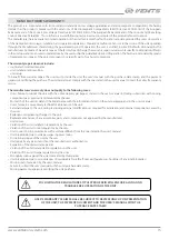
CONNECTION TO POWER MAINS

POWER OFF THE POWER SUPPLY PRIOR TO ANY OPERATIONS WITH THE UNIT.

THE UNIT MUST BE CONNECTED TO POWER SUPPLY BY A QUALIFIED ELECTRICIAN.

THE RATED ELECTRICAL PARAMETERS OF THE UNIT ARE GIVEN ON THE 

MANUFACTURER’S LABEL.

ANY TAMPERING WITH THE INTERNAL CONNECTIONS IS PROHIBITED  

AND WILL VOID THE WARRANTY.

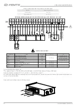
EXTERNAL WIRING DIAGRAM FOR THE VUTR 250/350/650 P/P2/PE/P2E EC A17/A18 UNIT

1    2    3    4     5    6    7    8    9   10  11  12  13 14  15  16  17 18  19  20     

Gnd R+ R- Gnd ~24V 0-10V Gnd ~24V NO NO

N

N

PE

L

L

N

L1

N

L1

NO

NO

NO

NO

2

2

2

1

1

1

PK1*

SM1*

2

1

1

2

2

1

Gnd

P1**    

 th-Tune

Rx+/T

x+

Rx

-/T

x-

Gnd

~

24V

~

{

{ {

N

L

2 1

SM1*

KN1*

TS1

HL1

CCU*

G

re

y

Black

Yello

w/g

reen

Blue

Br

own

Gr

een

Yello

w

Br

own

G

re

y

Whit

e

Po

wer input 

230 V

AC

0-10 

V indoor humidit

y

 sensor c

onnec

tion

Normally opened c

on

tac

from r

ela

y sensor or swit

ch


 —  ELECTRIC SHOCK HAZARD!

Designation

Name

Model

Wire**

SM1*

Supply air damper actuator

LF230

2x0.75 mm

2

SM2*

Exhaust air damper actuator

LF230

2x0.75 mm

2

PK1*

Contact from fire alarm panel

NC

2x0.75 mm

2

CCU*

CCU control

NO

2x0.75 mm

2

P1**

Control panel

th-Tune

2x0.75 mm

2

KH1*

Contact from kitchen hood

* Devices are not supplied with the unit, are available on separate order.
** The unit can be equipped with a th-Tune control panel
*** Wire cross-section at a cable length of maximum 100 m.

•  The unit is rated for connection to 230 V/50 (60) Hz power mains  according to the wiring diagram. 
•  The connection must be made using insulated conductors (cables, wires). The actual wire cross section selection must be based 

on the maximum load current, maximum conductor temperature depending on the wire type, insulation, length and installation 
method. 

•  The external power input must be equipped with a QF automatic circuit breaker built into the stationary wiring to open the circuit in 

the event of overload or short-circuit.  The position of the external automatic circuit breaker must ensure free access for quick power-off 
of the unit. The trip current of the automatic circuit breaker must exceed the maximum current consumption of the unit (refer to the 
“Technical data” section or on the unit label). The recommended trip current of the circuit breaker is the next current in the standard trip 
current row following the maximum current of the connected unit.  The automatic circuit breaker is not included in the delivery set and 
can be ordered separately.

Summary of Contents for VUTR 250 P EC

Page 1: ...VUTR 250 P P2 PE P2E EC VUTR 350 P P2 PE P2E EC VUTR 650 P PE EC Air handling unit USER S MANUAL...

Page 2: ...a 5 Design and operating principle 8 Installation and set up 9 Connection to power mains 11 Technical maintenance 13 Storage and transportation regulations 14 Manufacturer s warranty 15 Certificate of...

Page 3: ...electric parts of the unit against ingress of water Do not allow children to operate the unit Disconnect the unit from power mains prior to any technical maintenance Do not store any explosive or hig...

Page 4: ...t recovery air handling unit with a rotary heat exchanger PURPOSE The unit is designed to ensure continuous mechanical air exchange in houses offices hotels cafes conference halls and other utility an...

Page 5: ...VUTR 350 P2E EC VUTR 650 P EC 200 125 1542 1445 932 897 422 409 317 338 229 195 8 172 481 231 207 12 VUTR 650 PE EC The unit is designed for indoor application with the ambient temperature ranging fro...

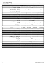
Page 6: ...ter mm 160 Weight kg 53 54 55 56 Heat recovery efficiency from 72 up to 87 from 71 up to 87 Heat exchanger type rotary SEC class A A A A Parameters VUTR 350 P2 EC VUTR 350 P2E EC VUTR 350 P EC VUTR 35...

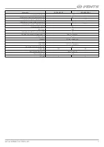
Page 7: ...Maximum unit current with a heater A 13 7 Maximum air flow m3 h 710 RPM min 1 3600 Sound pressure level at 3 m distance dBA 36 Maximum transported air temperature C from 25 up to 40 Casing material a...

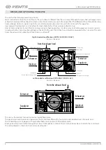
Page 8: ...kitchen hood should be equipped with an air valve The valve closes the exhaust duct when the kitchen hood is switched off Right handed modification VUTR 350 P 2 E EC R A21 service side view Supply ai...

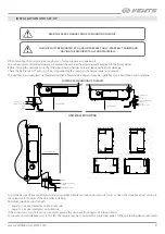
Page 9: ...l or may be rigidly fixed on a horizontal or vertical plane SUSPENDED MOUNTING OF THE UNIT Screw Vibration absorbing rubber Expansion anchor min 400 mm min 400 mm Nut Threaded rod Washer Vibration abs...

Page 10: ...urface as well as the weigh of the unit refer to the Technical data section Fasteners for unit mounting should be selected by the service technician HUMIDITY SENSOR MOUNTING The humidity sensor is not...

Page 11: ...Tune 2x0 75 mm2 KH1 Contact from kitchen hood Devices are not supplied with the unit are available on separate order The unit can be equipped with a th Tune control panel Wire cross section at a cabl...

Page 12: ...ZARD Designation Name Contact type Cable type Note S 1 Supply air damper actuator NO 2 x 0 75 mm2 3A 30DC 250 AC S 2 Exhaust air damper actuator NO 3A 30DC 250 AC 1 Contact from fire alarm panel NC Re...

Page 13: ...filters must be replaced For new filters contact the Seller Sequence of filter removal 1 Disconnect the unit from power mains 2 Unscrew the triangular screws holding the service covers 3 Remove the se...

Page 14: ...tem elements such as air ducts diffusers louvre shutters grilles Cold supply air The extract filter is soiled Clean or replace the extract filter The unit operates in Cooling mode Check the unit opera...

Page 15: ...ler for warranty service The manufacturer s warranty does not apply to the following cases User s failure to submit the unit with the entire delivery package as stated in the user s manual including s...

Page 16: ...16 VUTR 250 350 650 P P2 PE P2E EC www ventilation system com...

Page 17: ...17 www ventilation system com...

Page 18: ...18 VUTR 250 350 650 P P2 PE P2E EC www ventilation system com...

Page 19: ...s manual The warranty terms are acknowledged and accepted Customer s Signature The VUTR P__________EC A___ unit is installed pursuant to the requirements stated in the present user s manual Installat...

Page 20: ...V158EN 05...

Reviews: