background image

9

EN

MOUNTING 

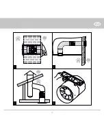
The fan is designed for vertical or horizontal installation and connection to a round air duct of a matching diameter, Fig. 1-3 
Attention!  In case of vertical mounting the fan must be protected against ingress of rainfalls and condensate inside the fan.  
Fan installation with direct air discharge upwards is not allowed, Fig. 3.
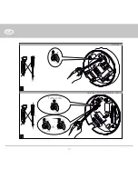
Use the supplied fixing bracket for mounting. 
Attachment of the fixing bracket to the fan is shown in Fig. 4. 
Fan mounting steps are shown in Fig. 5-12.
Wiring options are shown in Fig. 13-16.

WARNING – TO REDUCE THE RISK OF FIRE, ELECTRIC SHOCK, OR INJURY TO PERSONS, OBSERVE THE 

FOLLOWING:

• 

Use this unit only in the manner intended by the manufacturer. If you have questions, contact the 
manufacturer.

• 

Before servicing or cleaning unit, switch power off at service panel and lock the service disconnecting 
means to prevent power from being switched on accidentally. When the service disconnecting means 
cannot be locked, securely fasten a prominent warning device, such as a tag, to the service panel. 

• 

Installation work and electrical wiring must be done by qualified person(s) in accordance with all applicable 
codes and standards, including fire-rated construction. 

• 

When cutting or drilling into wall or ceiling, do not damage electrical wiring and other hidden utilities. 

• 

Ducted fans must always be vented to the outdoors. e) If this unit is to be installed over a tub or shower, 
it must be marked as appropriate for the application and be connected to a GFCI (Ground Fault Circuit 
Interrupter) – protected branch circuit”

• 

If this unit is to be installed over a tub or shower, it must be marked as appropriate for the application and 
be connected to a GFCI (Ground Fault Circuit Interrupter) – protected branch circuit

Summary of Contents for Quietline

Page 1: ...AXIAL FAN User s manual www vents us com Quietline 120V 60Hz EN...

Page 2: ...Brief description 6 Modifications 6 Operating guidelines 7 Designation key 8 Mounting 9 Electronic control logic 9 Timer adjustment 11 Technical maintenance 12 Storage and transportation regulations 1...

Page 3: ...me of the document s preparation The Company reserves the right to modify the technical characteristics design or configuration of its products at any time in order to incorporate the latest technolog...

Page 4: ...he fixed wiring system The gap between the circuit breaker contacts on all poles must be not less than 3 mm Check the unit for any visible damages of the impeller and the casing before starting instal...

Page 5: ...t put objects on it The unit is allowed to be used by children aged from 8 years old and above and persons with reduced physical sensory or mental capabilities or no experience and knowledge provided...

Page 6: ...designed for connection to 100 125 and 150 mm air ducts MODIFICATIONS Quietline k fan with a fixing bracket Quietline R fan with a power cable and a plug Quietline T fan with a controllable timer for...

Page 7: ...former for example TRF 120 12 25 not included in the delivery set available upon separate order The fan is rated for operation at the ambient air temperature from 41 F to 104 F Ingress protection rati...

Page 8: ...wo speed motor Q fan with a low speed motor 12 safety extra low voltage of 12 V 50 Hz Additional options T fan with a controllable timer for details please refer to electronic control logic K fan with...

Page 9: ...itch power off at service panel and lock the service disconnecting means to prevent power from being switched on accidentally When the service disconnecting means cannot be locked securely fasten a pr...

Page 10: ...s turned off in the initial position The fan starts operating at speed 2 as the external switch supplies a control signal to the LT input terminal for instance during switching the light on After the...

Page 11: ...perates at speed 1 in the initial position The fan switches to speed 2 after elapse of the set time as adjusted from 1 to 15 hours and runs at the speed 2 from 2 to 30 min then returns to the speed 1...

Page 12: ...er clockwise to decrease the turn off delay time respectively adjustable from 2 up to 30 minutes Operation mode 4 Tint To adjust the interval operation time rotate the control knob Tint clockwise to i...

Page 13: ...ventilated premise with temperature range from 41 F to 104 F Storage environment must not contain aggressive vapours and chemical mixtures provoking corrosion insulation and sealing deformation Use s...

Page 14: ...be defective under normal use and service This warranty does not cover a normal maintenance and normal service or b any products or parts which have been subject to misuse negligence accident imprope...

Page 15: ...ranty period is calculated from the production date The unit can be exchanged at the following address Bodor Vents LLC DBA VENTS US 11013 Kenwood Road Cincinnati Ohio 45242 Phone 513 348 3853 e mail s...

Page 16: ...16 EN 3 1 4 2 1 3 2...

Page 17: ...17 EN QF L N 6 7 8 9 10 5...

Page 18: ...15 16 2 1 S QF L N QF N N L L LT S 1 2 3 S N L QF S speed QF 1 N 3 L 2 S LT N L 13 14 15 16 Wiring diagrams 2 speed 2 3 speed 1 Quietline Quietline Quietline DUO Quietline 150 Extra Quietline DUO Qui...

Page 19: ...19 EN 18 17 2 min 30 min Toff 2 min 30 min Toff HS time 0 min 2 min Ton OR 1 hour 15 hour Tint Quietline Quietline DUO Quietline 150 Extra...

Page 20: ...20 EN...

Page 21: ...21 EN...

Page 22: ...22 EN...

Page 23: ...23 EN Quality Inspector s Stamp Manufacture Date Sold by name and stamp of the seller Purchase Date...

Page 24: ...Certificate of acceptance The fan is recognized as serviceable VUSA178 1EN 01 Quietline k 100 T DUO 125 K Extra 150 R Q 12...

Reviews: