background image

9

vents-us.com

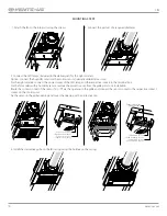
L = min 5 mm

L = min 5 mm

(

3

/

16

") 

(

3

/

16

") 

MOUNTING AND SET-UP 

READ THE USER'S MANUAL BEFORE INSTALLING THE UNIT

The fan is a component part and is not designed for stand-alone operation. 
The fan is constructed for ceiling installation in the floor slab and fixation to the inter joist with the distance between the ceiling joists from 
270 mm (10  

5

/

8

”) up to 680 mm (20  

3

/

4

”) using the removable fixing brackets or the fastening holes in the fan casing. 

The installation place must be in compliance with local construction norms for units of this type. 
Check the fan for mechanical damages prior to mounting . 
Make sure that the casing comprises no foreign objects, such as paper or foil. 
While mounting the fan sufficient service access for maintenance or repair operations must be provided. 
The minimum gap between the fan and the ceiling is 5 mm (

3

/

16

”).

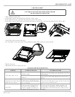
WARNING – TO REDUCE THE RISK OF FIRE, ELECTRIC SHOCK, OR INJURY TO PERSONS, OBSERVE THE FOLLOWING:

•  Use this unit only in the manner intended by the manufacturer. If you have questions, contact the 

manufacturer.

•  Before servicing or cleaning unit, switch power off at service panel and lock the service 

disconnecting means to prevent power from being switched on accidentally. When the service 
disconnecting means cannot be locked, securely fasten a prominent warning device, such as a tag, 
to the service panel. 

•  Installation work and electrical wiring must be done by qualified person(s) in accordance with all 

applicable codes and standards, including fire-rated construction. 

•  When cutting or drilling into wall or ceiling, do not damage electrical wiring and other hidden 

utilities. 

•  Ducted fans must always be vented to the outdoors. e) If this unit is to be installed over a tub or 

shower, it must be marked as appropriate for the application and be connected to a GFCI (Ground 
Fault Circuit Interrupter) – protected branch circuit”

•  If this unit is to be installed over a tub or shower, it must be marked as appropriate for the 

application and be connected to a GFCI (Ground Fault Circuit Interrupter) – protected branch 
circuit

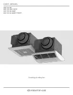
Summary of Contents for CBF 110

Page 1: ...CBF 110 130 CBF 110 130 T TH TP CBF 110 130 LIGHT CBF 110 130 LIGHT T TH TP Centrifugal ceiling fan USER S MANUAL...

Page 2: ...or to installing and operating the unit All user s manual requirements as well as the provisions of all the applicable local and national construction electrical and technical norms and standards must...

Page 3: ...ic parts of the unit against ingress of water Do not allow children to operate the unit Disconnect the unit from power mains prior to any technical maintenance Do not store any explosive or highly fla...

Page 4: ...s THE UNIT SHOULD NOT BE OPERATED BY CHILDREN OR PERSONS WITH REDUCED PHYSICAL MENTAL OR SENSORY CAPACITIES OR THOSE WITHOUT THE APPROPRIATE TRAINING THE UNIT MUST BE INSTALLED AND CONNECTED ONLY BY P...

Page 5: ...ing bracket 4 pcs Fastening kit 1 pc User s manual 1 pc Packing box 1 pc Ceileo 130 Light TP Additional options T timer TH humidity sensor and timer TP motion sensor and timer Basic options _ no integ...

Page 6: ...8 3 15 16 1 3 4 13 10 3 16 10 1 4 15 9 16 7 3 8 11 16 Ceileo 110 130 Light Ceileo 110 130 Light T TH TP 5 7 8 3 7 8 3 15 16 1 3 4 13 10 3 16 10 1 4 15 9 16 7 3 8 2 7 6 8 3 16 4 13 16 The unit is desi...

Page 7: ...73 SFP W l s 0 55 0 50 0 49 0 54 Weight kg 5 3 6 4 5 3 6 4 lbs 11 7 14 1 11 7 14 1 IP X4 SEC class D C For fans with light only TECHNICAL DATA CBF 110 130 DC T TH TP CBF 110 130 DC LIGHT T TH TP DESI...

Page 8: ...f the fan is turned on or goes to high speed after countdown of a set turn on delay time adjustable from 0 to 3 minutes After the fan is turned off it keeps running for a set turn off delay time adjus...

Page 9: ...E THE FOLLOWING Use this unit only in the manner intended by the manufacturer If you have questions contact the manufacturer Before servicing or cleaning unit switch power off at service panel and loc...

Page 10: ...dels with a humidity sensor remove the protective cap from the grille prior to its installation Route the contact socket of the sensor TH or TP via the opening in the grille and connect the sensor soc...

Page 11: ...of the ceiling joists Installation between the ceiling joists Fixation between the ceiling joists using the mounting brackets Additional fastening holes in the fan casing may be used for mounting pur...

Page 12: ...ERMINAL BOX FOR WIRING THE FAN L2 L1 N L N LT N L N L 1 2 3 4 5 6 7 LIGHT contact socket is available only for the models with LED light FAN 1 QF QF 120 V 60 Hz 120 V 60 Hz Remove the decorative grill...

Page 13: ...to navigate in the Setup menu Press to select a current entry in the Setup menu After that the indicator displays the selected parameter value e g turn off delay timer setting Use or to change the va...

Page 14: ...take the following values for the fan with an AC motor the fan is turned off the fan operates at reduced performance the fan operates at maximum performance Example 1 with these activated settings th...

Page 15: ...SIBLE REASONS TROUBLESHOOTING The fan does not get started No power supply Check the electric connections and the operation status of the circuit breaker Motor jam Turn the fan off Troubleshoot cloggi...

Page 16: ...machinery for handling and storage operations to prevent possible damage to the unit Follow the handling requirements applicable for the particular type of cargo The unit can be carried in the origina...

Page 17: ...recommended installation instructions Labor to remove and replace products is not covered The duration of any implied warranty is limited to the time period specified for the express warranty Some st...

Page 18: ...equirements stated in the present user s manual Installation Company Stamp Seller Address Phone Number Installation Technician s Full Name Installation Date Signature The unit has been installed in ac...

Page 19: ...19 vents us com...

Page 20: ...VUSA166 1EN 01...

Reviews: