background image

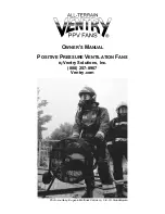
P

OSITIVE 

P

RESSURE 

V

ENTILATION 

F

ANS


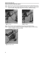
Step 5. Rock the fan onto the two retracted legs. 
Step 6. Loosen the leg lock handle on the extended leg, retract the leg, and then 

retighten the leg lock handle. 


Videos showing how to extend and retract the legs on a V

ENTRY 

F

AN

 can be seen on 

ventry.com. 

HOW TO USE POSITIVE PRESSURE VENTILATION  

PPV The Basics


Positive pressure ventilation (PPV) is a powerful tool for firefighting but, like a double-
edged sword, it can cut both ways. Training and careful planning are essential if PPV is 
going to work to its full potential. Remember the basic fire triangle (heat, air, fuel). PPV 
reduces the temperature by displacing the hot flammable gasses, but it also provides 
the fire with an abundant source of oxygen. Timing is the key: have everything ready for 
the initial attack before positive pressure is used. The size-up needs to be done, 
incident command needs to develop a plan which uses an aggressive initial attack, lines 
need to be setup and charged, and firefighters in SBA’s need to be ready to attack the 
fire seat.    

Use PPV to blow the heat and smoke out of the structure, then get in and put the fire 
out before the increase in oxygen has a chance to let the fire flair up. Figure 16 is a 
simple example of the fan's proper use. 

Figure 14. Step 5 

Figure 15. Step 6 

Summary of Contents for 20EM3550

Page 1: ...OWNER S MANUAL POSITIVE PRESSURE VENTILATION FANS By Ventry Solutions Inc 888 257 8967 Ventry com Photo courtesy Eugenio Martinez Carrasco C E I S Guadalajara ...

Page 2: ...y has helped make this fan the best on the market If you have any comments ideas observations or creative uses please contact us by phone email mail or fax so that we may continue to improve our product Fan Serial Number ____________________________________ Fan Size Model ______________________________________ Engine Serial Number _________________________________ Invoice Number __________________...

Page 3: ...ETY 9 Safety Guidelines 9 Ground Debris Pickup Maximum Air Volume 9 Stability 10 Filling the Gas Tank 10 Backdraft Situations 10 COMMON QUESTIONS ABOUT POSITIVE PRESSURE 10 Why positive instead of negative pressure ventilation 10 When should positive pressure not be used 10 What is the door seal and how important is it 11 What are some examples of positive pressure ventilation 11 FAN COMPARISON ME...

Page 4: ...LIST 24 INCH FRAME WITH AND WITHOUT WHEEL OPTION 17 24 Inch Frame Assembly Diagram 18 PARTS LIST FOR ENGINE TACH AND SPARK 19 Spark Arrester and Stickers Honda GX Series Engines 19 Spark Arrester and Stickers Honda GC Series Engines 19 Tachometer Hour Meter 20 PARTS LIST FOR GUARD REAR MOUNT 21 Guard Mount Pictures 21 PROPELLER ORIENTATION 23 PARTS LIST FOR PROPELLER MOUNT 23 Propeller Hubs and Ta...

Page 5: ...t it fixed and back in service quickly 888 257 8967 Ventry com Some of the pictures within this VENTRY FAN manual show older VENTRY FANS before the vertical handles and Solid Rubber Medium Flat Free Wheels with Stair Skids Should you have questions or need parts for you VENTRY FAN no matter the age please contact us ...

Page 6: ...try com rev20210415 Fan Specs SPECIFICATIONS ALL TERRAIN PPV FANS MOTOR MAKE HP RATINGS MODEL Pre 2007 Now Honda GX120 4 hp à 3 5 hp Honda GC160 5 hp à 4 6 hp Honda GX160 5 5 hp à 4 8 hp Honda GX200 6 5 hp à 5 5 hp Table 2 Table 1 Measurement not yet available Patent 5 503 526 l Smoke busting VENTRY SAFETY PROPELLERS Two blade aircraft propellers with vibration dampening wood cores and pressure bo...

Page 7: ...7 5 20GX120 60 64 66 70 69 5 73 5 20GC160 57 61 63 67 66 5 70 5 20GX160 66 72 72 78 75 5 81 5 24GX120 78 82 84 88 87 5 91 5 84 88 24GC160 64 68 70 74 73 5 77 5 70 74 24GX160 73 79 79 85 82 5 88 5 79 85 24GX200 88 94 90 5 96 5 92 98 WEIGHT Lbs Fan with Fan with wheels Fan with wheels Fan with wheels no wheels Small Solid Rubber Medium Flat Free Large Pneumatic MODEL 20EM3550 23 5 x 20 5 x 23 5 23 5...

Page 8: ...el and oil Oil amounts and specifications are listed in the engine manual under servicing All models use 0 63 quart of 10W 30 oil FAN TRANSPORT One Person Carry Face the propeller grip side handles with both hands and lift pressing guard against body Figure 1 Two Person Carry Left and right persons grasp corresponding side handles Figure 2 Figure 1 One Person Carry Figure 2 Two Person Carry ...

Page 9: ...m How to raise the fan with one person Step 1 Loosen all three leg adjustment knobs Step 2 Rock the fan on two legs one front and one rear allowing the other front leg to extend Step 3 Tighten the leg lock handle on the extended leg Step 4 Rock fan onto rear and extended front leg allowing the other front leg to extend Figure 3 Step 1 Figure 4 Step 2 Figure 5 Step 3 Figure 6 Step 4 ...

Page 10: ...e leg lock handle on the extended front leg Step 6 Rock the fan on the two extended legs while adjusting the remaining leg Step 7 Tighten rear leg and aim Step 8 Start fan and check stability Figure 7 Step 5 Figure 8 Step 6 Figure 9 Step 7 Figure 10 Step 8 ...

Page 11: ...hten the leg lock handle To assist with tightening the leg lock handle it may help to lower the fan onto the retracted rear leg Step 3 Rock the fan onto the retracted rear leg and one extended front leg Step 4 Loosen the leg lock handle of the leg not touching the ground retract the leg and then retighten the leg lock handle Figure 11 Step 1 Figure 12 Step 2 Figure 13 Steps 3 and 4 ...

Page 12: ...l potential Remember the basic fire triangle heat air fuel PPV reduces the temperature by displacing the hot flammable gasses but it also provides the fire with an abundant source of oxygen Timing is the key have everything ready for the initial attack before positive pressure is used The size up needs to be done incident command needs to develop a plan which uses an aggressive initial attack line...

Page 13: ...ze the structure starting at an upwind room Open a window and let the room completely clear of smoke Then close the window and entrance to that room Proceed in a downwind direction to clear the rest of the rooms in the structure The downwind technique prevents smoke from leaking back into rooms that have already been cleared and allows you to check for other fire seats if an upwind room refills wi...

Page 14: ...than into unaffected areas of the structure For example if the fire started burning near the front door set the fan up at a back door to blow the fire out the front door rather than all the way through the structure 4 Open a minimum of windows and doors for ventilation Having too many vents open will reduce the pressure inside the house and make positive pressure ventilation less effective The air...

Page 15: ...using a cloud of vaporized fuel to enter a burning structure Your imagination can picture the result Backdraft Situations Alternate ventilation techniques are necessary in the case of a backdraft situation in which the use of a VENTRY FAN is not recommended After the backdraft situation has been rectified the VENTRY FAN can be used COMMON QUESTIONS ABOUT POSITIVE PRESSURE Why positive instead of n...

Page 16: ... we re happy to get back to bed promptly with a minimum of excitement Another favorite of ours is a smoldering attic fire caused by a faulty chimney or the old dime behind a fuse trick Without creating a vent opening we use the fan to pressurize the house Enough air will leak into the attic to clear the smoke so that we can locate the individual curls of smoke that mark the hot spots We then use a...

Page 17: ...rm a thrust test A flat board strong enough to hold the fan plywood works great Two dowels any long rounded pole even broomsticks will do A fish scale preferably digital with which to measure thrust Find a smooth flat surface like a shop floor with lots of room around it Place the two dowels on the surface parallel to each other Upon these place the flat board Check to make sure that the board rol...

Page 18: ...page 20 TROUBLE SHOOTING Fan walks during operation Worn out Rubber Leg Ends Look to see if the leg ends feet are worn out If they have a lot of wear you may be able to rotate them on the end of the legs This will place a new section of rubber into service Otherwise contact Ventry Solutions for a new pair or you can pick up a new set at your local medical supply outlet Out of Balance Propeller An ...

Page 19: ...the frame where the leg slides through If needed lightly file this area to remove any roughness c File the inside of the frame where the leg adjustment handle is inserted d Reinsert the leg into the frame followed by the roll pin into the top of the leg 4 Check the frame and leg for any abnormal bends If the adjustable leg still does not slide freely replacement may be necessary Fan too large to f...

Page 20: ...g foam handle 1 24 F 7N04C Tubing nut 1 PARTS LIST 20 INCH FRAME WITH WHEEL AND HANDLE OPTION Reference Part Number Number Quantity 01 F 1009 Leg cap inch 6 02 F 1004S 20 inch Leg rear 1 04 F 33827 Hand activated plunger 1 05 F 1021 Towing handle lock nut washer spring 1 06 F 1022 Towing handle 1 07 F 1010 Short foam handle 5 08 F 1018 7 8 Round cap 4 09 F 1012 20 inch seven handle left 1 10 942SB...

Page 21: ...20 Inch Frame Assembly Diagram this is for the original wheel handle option design on VENTRY FANS Please contact Ventry Solutions Inc if your fan as the vertical handle and stair skids Figure 20 20 inch frame assembly diagram ...

Page 22: ... HANDLE OPTION Reference Part Number Number Quantity 01 F 1009 Leg cap inch 6 02 F 1004L 24 inch Leg rear 1 04 F 33827 Hand activated plunger 1 05 F 1021 Lock nut washer spring for towing handle 1 06 F 1022 Towing handle 1 07 F 1010 Short foam handle 4 08 F 1018 7 8 Round cap 4 09 F 1015 24 inch seven handle right 1 10 942SB Rubber leg ends feet 3 11 F 1023 5 16 Wheel mounting hardware bolts washe...

Page 23: ...24 Inch Frame Assembly Diagram this is for the original wheel handle option design on VENTRY FANS Please contact Ventry Solutions Inc if your fan as the vertical handle and stair skids Figure 21 24 inch frame assembly diagram ...

Page 24: ... one of the following E GX120 Honda 3 5 HP 1 E GX160QX2 Honda 4 8 HP 1 E GX160QXS2 Honda 4 8 HP with alternator 1 E GX200QX2 Honda 5 5 HP 1 E GX200QG2 Honda 5 5 HP with alternator 1 Spark Arrester Stickers and Honda GC160 Engine Reference Part Number Number Quantity 02 E DA14 Address decal 1 03 E DC13 Caution decal 1 06 E GC160 Honda 4 6 HP 1 07 S 1036 Spark arrester Honda GC160 engines w screw 1 ...

Page 25: ...eter Hour Meter Reference Part Number Number Quantity 01 T 1031 Tiny Tach 1 02 T 1032 Self tapping screws 8 x 3 8 2 03 T W075 Wire ties 50 test 2 04 Motor Mount Bolt holding Grounding Clip 1 Figure 24 Tachometer Hour Meter assembly ...

Page 26: ...rd mount spacers for Honda GX series motors 4 G 1036 Guard mount spacers for Honda GC160 motors 4 07 G 1021 5 16 SAE washers GD8 12 08 G 1020 5 16 Split lock washer GD8 4 09 G 1032 Nylock GD8 2 10 G 1037 Neobond washers 4 11 Guard Rear one of the following QUABU120R 20 inch fan rear guard 1 QUABU124R 24 inch fan rear guard 1 12 Engine see pages 19 and 20 1 13 Frame see pages 15 18 14 G 1027 SAE wa...

Page 27: ...ortant to keep everything lined up properly especially for the 5 16 bolts attaching the guard to the motor crank case If you leave out washers the 5 16 bolts can go to deep into the blind holes and can break the engine crank case Please be careful Figure 26 Close up of guard mount to engine Figure 27 Close up of guard mount to frame ...

Page 28: ...5 P 1025 Hub aluminum 1 06 E H002 Engine key 1 07 P 1030 Crush plate 1 08 P 1031 Cap screws 5 16 inch x 3 inch 4 09 P 1032 Retention washers 4 10 Propellers one of the following P20 1 5E 20 inch EM3550 wood Kevlar fiberglass composite 1 P20 120 20 inch GX120 wood Kevlar fiberglass composite 1 P20 160 20 inch GX160 GC160 wood Kevlar fiberglass composite 1 P24 120 24 inch GX120 wood Kevlar fiberglas...

Page 29: ...VENTRY SOLUTIONS INC 24 Propeller Hubs and Tab Washer Pictures Figure 28 Figure 29 Figure 30 Crush plate ...

Page 30: ...eference Part Number Number Quantity 01 Guard Front one of the following QUABU120F 20 inch Fan guard front 1 QUABU124F 24 inch Fan guard front 1 02 G W075 VENTRY FAN sticker 1 03 G 1040 Nylon lock nut and SAE washer 4 Guard Front Picture Figure 31 Guard Front picture ...

Page 31: ...3 Lower light mounting hardware 1 05 Frame see pages 15 18 06 L 1004 Fuse holder 1 07 L 1005 Electrical tape 1 08 T W079 Wire tie 1 09 L 1006 Wire 1 10 L 1007 Star washer and ring tong terminal 1 11 L 1009 Spade connectors 2 Light one of the following 12 H 7614 Halogen 1 12 TL LED LED 1 Light Option Pictures Halogen Light shown Contact Ventry Solutions Inc for details on the LED Light Figure 32 Ha...

Page 32: ...rew engine mounting bolts 17 to 21 inch x inch Cap screw rear guard to guard mount tubing 9 to 11 5 16 inch Cap screw rear guard to aluminum engine block 8 to 10 Propeller hub set screw 9 to 11 5 16 inch x inch Cap screw propeller safety bolt 17 to 21 5 16 inch x 3 inch Cap screw propeller bolts 10 to 12 ...

Reviews: