


D-2
MAIN TE NANCE
Re moval and Re in stal la tion of Mower Blades
for Sharpening or Re place ment:
Wear Heavy Gloves.
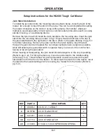
1. With the deck fully raised, place the tractor on a level surface. Set the
parking brake and remove the key from the tractor.
2. Remove the latch pins, and lift the deck to the near vertical position.
Reinstall the latch pins.
Note:
Interference of cover shield can be eliminated by removing the hinge
“hair pin” and then the cover shield.
3. To prevent blade rotation when removing blades, place a piece of wood
between the end of the blade and an appropriate structural part on the
underside of the deck.
4. Loosen the blade bolt and remove the blade for sharpening or replacement.
Note:
To remove, turn the left and center spindle bolts clockwise and the right
counterclockwise when facing the bolt head.
5. When installing a blade, the wood block must be placed on the opposite
side to prevent rotation. Tighten so that blade is firmly held in place.
(Approximately 65 ft/lbs)
Remember
: Use the correct right and left hand
bolts as described in #4.
Note:
Additional tightening will occur while mowing. This is natural because
of rotational torque.
6. Always install the spindle guard between the bolt head and the bottom of the
blade. This serves as a support washer as well as a device to minimize
bearing damage from wrapped string or wire.
Sharpening Blades:
Blades should be sharpened and balanced by a professional. Maintain balance
and the same bevel and length of sharpened surface.
Note:
The “Tough-Cut” mower has 3 bi-directional blades. The unused side of
each blade becomes the cutting edge by switching blades to a spindle of the
opposite rotation.
Stor age:
Before the mower is stored, thoroughly clean both the underside of the deck
and any accumulated clippings or debris on the top side.
Summary of Contents for Ventrac HQ680
Page 17: ...PARTS MANUAL HQ680 ...
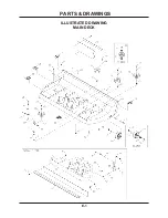
Page 18: ...ILLUSTRATED DRAWING MAIN DECK E 1 PARTS DRAWINGS ...
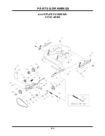
Page 20: ...ILLUSTRATED DRAWING HITCH ARMS E 3 PARTS DRAWINGS ...
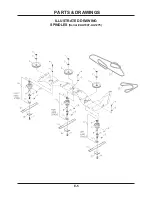
Page 22: ...ILLUSTRATED DRAWING SPINDLES Serial AA1007 AA1275 E 5 PARTS DRAWINGS ...
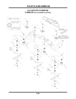
Page 24: ...ILLUSTRATED DRAWING SPINDLES Serial AB1276 AC1635 E 5b PARTS DRAWINGS ...
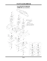
Page 26: ...ILLUSTRATED DRAWING SPINDLES Serial AD1636 E 5c PARTS DRAWINGS ...
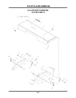
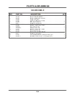
Page 28: ...ILLUSTRATED DRAWING COVER SHIELD E 7 PARTS DRAWINGS ...
Page 30: ...ILLUSTRATED DRAWING 70 8054 SWIVEL WHEEL KIT F 1 PARTS DRAWINGS ...


