


C-2
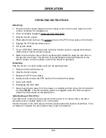
Attaching:
1. Drive the tractor slowly forward into the mating arms on the mower. Align the hitch
arms to complete the engagement.
2. Once completely engaged, close the front hitch latch.
3. Stop the tractor engine.
4. Place attachment belt over the outside groove of the PTO drive pulley on the tractor.
5. Engage the PTO spring tension lever.
6. Lift up jack stand.
7. If your VENTRAC 4000 series has a traction transfer system, engage according to
instructions in tractor owner’s manual.
8. Make sure the tractor has enough counterweight installed to keep the rear tires on
the ground at all times. The amount of counterweight needed will depend on the
terrain, slopes, and the manner in which the tractor is operated.
Detaching:
Park the tractor on a level surface and set the parking brake.
1. Raise the deck all the way up.
2. Stop the tractor engine.
3. Release the PTO lever slowly.
4. Dismount and remove the PTO belt from the tractor drive pulley.
5. Lower jack stand.
6. Disengage the hitch latch.
7. Slowly back tractor away from the mower or carefully pull the mower from the tractor
by hand.
NOTE:
If traction transfer system is engaged, lower the hitch enough to
relieve the lift pressure on the attachment.
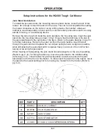
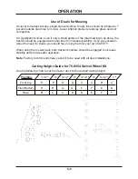
Initial Setting of Hitch Pins:
Four Hitch pins control the fore-to-aft level of the deck. On a hard surface, the deck
should be level or slightly higher (1/4”) at the back.
Position the pins in the hitch area so that the deck retains this position at all times. If the
cut height is changed, the pin locations may need to be altered.
OP ER ATING IN STRUC TIONS
OP ER A TION
Summary of Contents for Ventrac HQ680
Page 17: ...PARTS MANUAL HQ680 ...
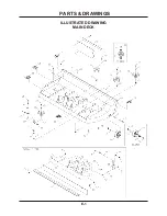
Page 18: ...ILLUSTRATED DRAWING MAIN DECK E 1 PARTS DRAWINGS ...
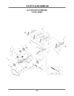
Page 20: ...ILLUSTRATED DRAWING HITCH ARMS E 3 PARTS DRAWINGS ...
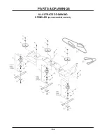
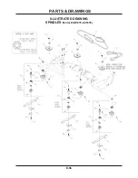
Page 22: ...ILLUSTRATED DRAWING SPINDLES Serial AA1007 AA1275 E 5 PARTS DRAWINGS ...
Page 24: ...ILLUSTRATED DRAWING SPINDLES Serial AB1276 AC1635 E 5b PARTS DRAWINGS ...
Page 26: ...ILLUSTRATED DRAWING SPINDLES Serial AD1636 E 5c PARTS DRAWINGS ...
Page 28: ...ILLUSTRATED DRAWING COVER SHIELD E 7 PARTS DRAWINGS ...
Page 30: ...ILLUSTRATED DRAWING 70 8054 SWIVEL WHEEL KIT F 1 PARTS DRAWINGS ...


