background image

HEI240 Wood Insert Fireplace Installation and Operation Manual 

29 

Clearances to Combustible Material


The  clearances  shown  in  this  section  have  been  determined  by  test  according  to 

procedures set out in safety standards ULC S628 (Canada), UL1482 (U.S.A.) and UL737 

(U.S.A.).  

When the insert is installed so that its surfaces are at or beyond the minimum clearances 

specified,  combustible  surfaces  will  not  overheat  under  normal  and  even  abnormal 

operating conditions.  

No  part  of  the  insert  may  be  located  closer  to  combustibles  than  the  minimum 
clearance figures given. 

8.1


Location of the Certification Label 

Since  the  information  given  on  the  certification  label  attached  to  the  appliance  always 

overrides  the  information  published  in  any  other  media  (owner’s  manual,  catalogues, 

flyers, magazines and/or web sites), it is important to refer to it in order to have a safe and 

compliant installation. In addition, you will find information about your insert (model, serial 

number, etc.). You can find the certification label to the front on the outside of the air jacket 

of the insert. 

To access the certification label, the faceplate may need to be removed. Therefore, we 

recommend that you note the insert’s serial number on this manual, since it will be needed 

to precisely identify the version of the appliance in the event you require replacement parts 

or technical assistance. 

8.2


The Masonry Fireplace Throat Damper 

If  the  fireplace's  draft  control  system  is  to  remain  in  the  masonry  fireplace,  it  must  be 

locked open for access of the chimney liner or removed entirely. If you remove draft control 

system from the masonry hearth, you will need to install the metal plate (27009), supplied 

with the owner’s manual kit, indicating that the masonry hearth has been modified. It must 

be secured inside the masonry hearth, in a visible place and easy to locate. 


8.3


Installation of a Combustible Mantel Shelf 

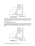
It is possible to install a combustible shelf with a maximum depth of 12" at a height of at 

least 27" above the insert. At a height of more than 27 ", the shelf must still have a depth 

of 12" maximum. Refer to the following figure. 

Summary of Contents for HEI240

Page 1: ...w occanada com en Manufactures by Stove Builder International Inc 250 rue de Copenhague St Augustin de Desmaures Quebec Canada G3A 2H3 Customer Service 418 908 8002 E mail tech sbi international com This manual is available for free download on the manufacturer s web site It is a copyrighted document Re sale is strictly prohibited The manufacturer may update this manual from time to time and canno...

Page 2: ...on making a wise purchase If this insert is not properly installed combustible materials near it may overheat To reduce the risk of fire follow the installation instructions in this manual exactly Contact local building or fire officials about restrictions and installation inspection requirements in your area Please read this entire manual before you install and use your new insert You may need to...

Page 3: ... 3 2 3 Log Length 14 3 2 4 Piece Size 14 3 2 5 How to Dry Firewood 15 3 2 6 Judging Firewood Moisture Content 15 3 3 Manufactured Logs 16 4 Operating Your Insert 16 4 1 The Use of a Fire Screen 16 4 2 Your First Fires 16 4 3 Lighting Fires 17 4 3 1 Conventional Fire Starting 17 4 3 2 The Top Down Fire 17 4 3 3 Two Parallel Logs 18 4 3 4 Using Fire Starters 18 4 4 Maintaining Wood Fires 18 4 4 1 Ge...

Page 4: ...tibles and Floor Protector 34 9 The Venting System 36 9 1 General 36 9 2 Block Off Plate 36 9 3 Suitable Chimneys 37 9 4 Liner Installation 37 9 5 Chimney Liner Installation 38 9 5 1 If the chimney liner does align with the insert s flue outlet you have two options 38 9 5 2 If the chimney liner does not align with the insert s flue outlet 39 9 6 Minimum Chimney Height 39 9 7 The Relationship Betwe...

Page 5: ...se invoice must be kept The date indicated on it establishes the warranty period If it cannot be provided the warranty period will be determined by the date of manufacture of the product It is also highly recommended to register the warranty online at http www occanada com en service support warranty registration Registering the warranty will help quickly find the information needed on the unit ...

Page 6: ...6 HEI240 Wood Insert Fireplace Installation and Operation Manual Certification Plate ...

Page 7: ...ocedures or reloading Always close the door or put back the fire screen after ignition Do not leave the insert unattended when the door is opened with or without fire screen NEVER USE GASOLINE LANTERN FUEL NAPHTHA FUEL OIL MOTOR OIL KEROSENE CHARCOAL LIGHTER FLUID OR SIMILAR LIQUIDS OR AEROSOLS TO START A FIRE IN THIS INSERT KEEP ALL SUCH LIQUIDS OR AEROSOLS WELL AWAY FROM THE INSERT WHILE IT IS I...

Page 8: ...ned by the manufacturer as its capacity to maintain a minimum acceptable temperature in the designated area in case of a power failure 1 Values are as measured per test method except for the recommended heating area firebox volume maximum burn time and maximum heat output 2 The maximum heat output dry cordwood is based on a loading density varying between 15 lb ft3 and 20 lb ft3 Other performances...

Page 9: ...2 UL 737 Canadian standard safety ULC S628 East west through the door you see the longitudinal sides of the logs north south through the door you see the tips of the logs Tested and certified in compliance with CFR 40 part 60 subpart AAA section 60 534 a 1 ii and Draft ASTM WK47329 14 Mobile home Canada or manufactured home USA The US department of Housing and Urban Development describes manufactu...

Page 10: ...10 HEI240 Wood Insert Fireplace Installation and Operation Manual ...

Page 11: ...entation Place a medium log about 3 x 3 on top of the biggest one Place another medium on coal bed on front of the biggest with another medium on top of it Place the last medium one in front If you need to stack the last piece over the ash lip make sure you always leave at least 1 5 8 inch between the last log and the inner wall of the combustion chamber There should be air space between each log ...

Page 12: ...mum benefit of the heat it produces and will achieve the highest possible heating efficiency and comfort The space where you spend most of your time will be warmest while bedrooms and basement if there is one will stay cooler In this way you will burn less wood than with other forms of heating Although the insert may be able to heat the main living areas of your house to an adequate temperature we...

Page 13: ... thus eliminating the need to mine new materials The paint coating on your insert is very thin Its VOC content Volatile Organic Compounds is very low VOCs can be responsible for smog so all the paint used during the manufacturing process meets the latest air quality requirements regarding VOC reduction or elimination The air tubes are stainless steel which can also be recycled Vermiculite is used ...

Page 14: ... Good Firewood Good firewood has been cut to the correct length for the insert split to a range of sizes and stacked in the open until its moisture content is reduced to 15 to 20 per cent 3 1 2 Tree Species The tree species the firewood is produced from is less important than its moisture content The main difference in firewood from various tree species is the density of the wood Hardwoods are den...

Page 15: ...re even slightly too long make loading the insert very difficult The most common standard length of firewood is 16 400 mm The pieces should be a consistent length with a maximum of 1 25 mm variation from piece to piece 3 1 4 Piece Size Firewood dries more quickly when it is split Large unsplit rounds can take years to dry enough to burn Even when dried unsplit logs are difficult to ignite because ...

Page 16: ... to dry than hardwoods softwoods like pine spruce and poplar aspen can be dry enough to burn after being stacked in the open for only the summer months hardwoods like oak maple and ash can take one or even two years to dry fully especially if the pieces are big firewood dries more quickly when stacked in the open where it is exposed to sun and wind it takes much longer to dry when stacked in a woo...

Page 17: ...ly secured on the stove to avoid any risk of fire When the fire screen is in use it is important not to leave the stove unattended to respond promptly in the event of smoke spillage into the room Potential causes of smoke spillage are described in Section 9 The Venting System of this manual See Appendix 6 Installing the Fire Screen for installation instructions OPERATING WITH THE FIRE SCREEN INCRE...

Page 18: ...od DO NOT LEAVE THE INSERT UNATTENDED WHEN THE DOOR IS SLIGHTLY OPENED ALWAYS CLOSE AND LATCH THE DOOR AFTER THE FIRE IGNITES After the kindling fire has mostly burned you can add standard firewood pieces until you have a fire of the right size for the conditions 4 3 2 The Top Down Fire The top down fire method solves two problems with the conventional method first it does not collapse and smother...

Page 19: ...ating with wood Do not expect steady heat output from your insert It is normal for its surface temperature to rise after a new load of wood is ignited and for its temperature to gradually decline as the fire progresses This rising and falling of temperature can be matched to your household routines For example the area temperature can be cooler when you are active such as when doing housework or c...

Page 20: ... 4 4 3 Raking Charcoal Rekindle the fire when you notice that the room temperature has fallen You will find most of the remaining charcoal at the back of the firebox furthest from the door Rake these coals towards the door before loading There are two reasons for this raking of the coals First it concentrates them near where most of the combustion air enters the firebox and where they can ignite t...

Page 21: ...he heat energy in the fuel over a longer period Second the flow rate of exhaust through the insert and flue pipe slows down which gives more time for the transfer of heat from the exhaust You will notice that as you reduce the air setting the flames slow down This is your indication that the insert is burning at its peak efficiency If the flames get small and almost disappear when you turn down th...

Page 22: ...he house 4 5 1 2 Long Lasting Low Output Fires Sometimes you will want to build a fire to last up to eight hours but don t need intense heat In this case use soft wood species and place the logs compactly in the firebox so the pieces are packed tightly together You will need to fire the load hot for long enough to fully char the log surfaces before you can turn the air down Make sure the fire is f...

Page 23: ... the logs east west East west loads that are built compactly break down slowly when heated but the amount of wood you can load is limited because if you put in too many pieces one may fall against the glass East west loads are excellent for long low output fires for relatively mild weather North south loads break down more quickly but much more wood can be loaded at a time This makes north south l...

Page 24: ...uous fire Use the technique described above for building a fire to take the chill off the house If you do get brown stains on the glass you can remove them with special cleaners for wood heater glass doors Do not use abrasives to clean your insert s door glass The deposits that form on the glass are the best indication of the quality of your fuel and how well you are doing in operating the insert ...

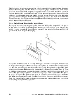
Page 25: ... is flat adhesive backed woven fibreglass Remove the 7 screws A glass retainers B and C Lift out the glass D from the door frame E and pull off the old gasket This is a good time to clean the glass thoroughly The gasket must be centred on the edge of the glass To do this easily peel back a section of the paper covering the adhesive and place the gasket on a table with the adhesive side up Stick th...

Page 26: ...smoke can condense inside the chimney liner and chimney forming a combustible deposit called creosote If creosote is allowed to build up in the venting system it can ignite when a hot fire is burned in the insert and a very hot fire can progress to the top of the chimney Severe chimney fires can damage even the best chimneys Smouldering smoky fires can quickly cause a thick layer of creosote to fo...

Page 27: ...plastic brushes The brush is forced up and down inside the chimney flue to scrub off the creosote The chimney should be checked regularly for creosote build up Inspection and cleaning of the chimney can be facilitated by removing the baffle CAUTION OPERATION OF YOUR HEI240 WITHOUT THE BAFFLE MAY CAUSE UNSAFE AND HAZARDOUS TEMPERATURE CONDITIONS AND WILL VOID THE WARRANTY NOTE Before installing the...

Page 28: ...ation Masonry or steel including the damper plate may be removed from the smoke shelf and adjacent damper frame if necessary to accommodate the insert s chimney liner provided that their removal will not weaken the structure of the fireplace and chimney and will not reduce protection for combustible materials to less than that required by the building code 2 CHIMNEY CAPS Mesh type chimney caps mus...

Page 29: ... AND MASONRY FIREPLACE CONFORMING TO BUILDING CODES FOR USE WITH SOLID FUEL DO NOT REMOVE BRICKS OR MORTAR FROM THE EXISTING FIREPLACE WHEN INSTALLING THE INSERT 7 1 Regulations Covering Insert Installation When installed and operated as described in these instructions the HEI240 wood insert is suitable for use in residential installations The HEI240 wood insert is not intended for installation in...

Page 30: ...erial number etc You can find the certification label to the front on the outside of the air jacket of the insert To access the certification label the faceplate may need to be removed Therefore we recommend that you note the insert s serial number on this manual since it will be needed to precisely identify the version of the appliance in the event you require replacement parts or technical assis...

Page 31: ... measurements specified in the table floor protection from section 8 5 To determine the need to add floor protection D beyond the hearth extension you must do the following calculation using the data in the table below D B A C Data for Floor Protection Calculation MAXIMUM EXTENDED A B Note 1 C D E AIR JACKET INCHES Dimension of the hearth extension See 8 4 1 and 8 4 2 5 D B A C 9 Flush with firepl...

Page 32: ...gh If the value D is positive you will need floor protection in front of the hearth extension at least equivalent to the result D 8 4 1 Installation raised 5 and less If non combustible material floor protection needs to be added in front of and level with the hearth extension of the masonry fireplace F 5 and less an R factor equal to or greater than 1 00 is required and should extend at least 23 ...

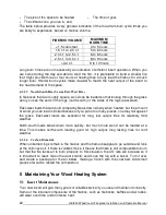
Page 33: ... are two ways to calculate the R factor of the floor protection First by adding the R values of materials used or by the conversion if the K factor and thickness of the floor protection are given To calculate the total R factor from R factors of the materials used simply add the R values of materials If the result is equal to or greater than the R value requirements the combination is acceptable T...

Page 34: ...ER INCH RESISTANCE R PER INCH THICKNESS Micore 160 0 39 2 54 Micore 300 0 49 2 06 Durock 1 92 0 52 Hardibacker 1 95 0 51 Hardibacker 500 2 3 0 44 Wonderboard 3 23 0 31 Cement mortar 5 00 0 2 Common brick 5 00 0 2 Face brick 9 00 0 11 Marble 14 3 20 00 0 07 0 05 Ceramic tile 12 5 0 008 Concrete 1 050 0 950 Mineral wool insulation 0 320 3 120 Limestone 6 5 0 153 Ceramic board Fibremax 0 450 2 2 Hori...

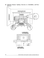
Page 35: ...34 HEI240 Wood Insert Fireplace Installation and Operation Manual 8 5 Minimum Masonry Opening Clearances to Combustibles and Floor Protector ...

Page 36: ...round and Mantel Shelf Heat Shield Installation for detail Where a fresh air intake is needed we suggest you add a minimum of 4 to the width of the minimum masonry opening Note 1 From door opening The depth of the hearth extension in front of the insert is included in the calculation of the floor protector s dimensions The masonry hearth should be at least 5 127 mm higher than the combustible floo...

Page 37: ... Block Off Plate To reduce the possibility of a cold air draft from the masonry chimney to get into the room when the insert in not working the installation of a sheet metal block off plate A in the drawing below is recommended Once you have made the block off plate to the proper dimension cut the pipe hole slightly larger than the liner s diameter and then install the liner through this hole Set ...

Page 38: ... of a chimney liner rigid or flexible to ensure satisfactory performance To ensure an optimal draft we also strongly recommend adding a minimum of 12 rigid liner between the top of the masonry chimney and the rain cap In all cases liners should be installed in accordance with the liner manufacturer s instructions including instructions for extension above the masonry Use Listed Chimney Liners UL 1...

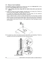
Page 39: ...s instructions To connect the chimney liner starter adapter to the flue outlet you can install the brackets with the screws that are in the owner s manual kit Using a powered driver secure the three brackets with the three screws provided 30131 on top of the insert in the three holes in front of the flue outlet The long end of the brackets must be attached to the insert Insert the chimney liner in...

Page 40: ...nstall a liner offset adapter secure the three brackets with the three screws provided 30131 on top of the insert in the three holes in front of the flue outlet The long end of the brackets must be attached to the insert The brackets and screws are in the insert s owner s manual kit Then follow the instructions in the manual provided with the liner offset adapter kit 9 6 Minimum Chimney Height The...

Page 41: ...ouse will compete against the desired upward flow in the chimney There are two reasons why the chimney in the house at right will cold backdraft when it is cold outside and there is no fire burning in the insert First the chimney runs up the outside of the house so the air in it is colder and denser than the warm air in the house And second the chimney is shorter than the heated space of the house...

Page 42: ...s to combustion air is if the operation of a powerful exhaust device such as a kitchen range exhaust causes the pressure in the house to become negative relative to outdoors If you do install an air supply through the wall of the house be aware that its pressure can be affected during windy weather If you notice changes in wood insert performance in windy weather and in particular if smoke puffs f...

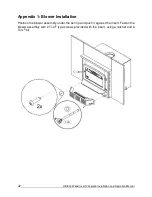
Page 43: ...tion and Operation Manual Appendix 1 Blower Installation Position the blower assembly under the ash lip and push it against the insert Fasten the blower assembly with 2 Torx type screws provided with the insert using a ratchet and a Torx bit ...

Page 44: ...late A located on the left or right side of the convection air jacket Choose the side that is best for your installation Then install the fresh air kit adapter B using 4 screws C Secure the flexible pipe E The pipe must be HVAC type insulated and must comply with ULC S110 and or UL 181 Class 0 or Class 1 to the adapter B using one of the adjustable pipe clamps D Secure the other end of the pipe to...

Page 45: ...finished side down on a flat soft non abrasive surface Line up the holes from of the upper panel with the holes of side panel and secure them together using the bolts and nuts provided Repeat this operation to assemble the other side panel Note If the installation of a heat radiation shield is required to reduce clearances from the shelf and top surround refer to Appendix 4 Top Surround and Mantel...

Page 46: ...rt Center the insert into the fireplace opening Adjust its height using the leveling bolts on each side of the convection air jacket box until the faceplate is properly seated on the floor of the hearth extension Then install one faceplate retainer spring on each side of the faceplate and attach the other end of the spring to the brackets on the left and right sides of the insert as shown in DETAI...

Page 47: ...nd as followed refer to Section 8 3 Compliance of a Combustible Mantel Shelf for additional details MAXIMUM MANTEL SHELF DIMENSION X MANTEL SHELF CLEARANCES I TOP SURROUND CLEARANCES H 12 305 mm 21 533 mm 21 533 mm Install the heat shield on the faceplate assembled with the faceplate extension using 3 self drilling screws included in the kit The heat shield should be pointing upwards Once the heat...

Page 48: ...APPENDIX 5 LOG RETAINERS INSTALLATION 1 2 3 47 HEI240 Wood Insert Fireplace Installation and Operation Manual ...

Page 49: ...andles and bring it close to the door opening Lean the upper part of the fire screen against the top door opening making sure to insert the top fire screen brackets behind the primary air deflector as in DETAIL A Lift the fire screen upwards and push the bottom part towards the stove then let the fire screen rest on the bottom of the door opening Warning Never leave the stove unattended while in u...

Page 50: ... the left end of the tube into the rear left channel 2 Align the notch in the left end of the tube with the key of the left air channel hole Using a Wise grip hold the tube and lock it in place by turning the tube as shown in DETAIL A Make sure the notch reaches the end of the key way 3 Repeat steps 1 and 2 for the two tubes in the back then install the baffle before installing the two front tubes...

Page 51: ...HEI240 Wood Insert Fireplace Installation and Operation Manual 50 Note that any secondary air tubes A can be replaced without removing the baffle board B and all tubes are identical ...

Page 52: ...o be removed To remove your insert follow these instructions Remove the faceplate retainer springs B holding the faceplate C to the Insert Remove the faceplate by pulling it towards you Remove the blower assembly D Remove the three screws securing the pipe connector A Unscrew the leveling bolts E located on each side of the insert Move the insert to perform maintenance ...

Page 53: ...HEI240 Wood Insert Fireplace Installation and Operation Manual 52 Appendix 9 Exploded Diagram and Parts List ...

Page 54: ...810 ARCHED REPLACEMENT GLASS WITH GASKET 9 1 16 X 9 9 16 X 17 5 16 1 11 AC06400 3 4 FLAT X 6 BLACK SELF ADHESIVE GLASS GASKET 1 12 PL55105 GLASS RETAINER FRAME 1 13 PL55106 GLASS RETAINER FRAME 2 14 30124 SCREW 8 32 X 5 16 TRUSS QUADREX ZINC 7 15 PL65582 ASH LIP 1 16 30060 THREAD CUTTING SCREW 1 4 20 X 1 2 F HEX STEEL SLOT WASHER C102 ZINC 6 17 SE65584 FAN ASSEMBLY 130 CFM 115V 60Hz 1 18 44070 CRO...

Page 55: ...ING 1 2 OUTSIDE DIA X 3 L 2 42 PL65794 UPPER AIR DEFLECTOR 1 43 PL65505 TOP AIR DEFLECTOR PROTECTOR 1 44 29010 4 1 2 X 9 X 1 1 4 REFRACTORY BRICK 17 45 PL36098 BRICK 2 1 4 X 4 X 1 1 4 2 46 PL36236 4 1 2 X 3 3 4 X 1 1 4 REFRACTORY BRICK 1 47 PL65514 SECONDARY AIR TUBE 1 48 PL65514 SECONDARY AIR TUBE 1 49 PL65514 SECONDARY AIR TUBE 1 50 PL65514 SECONDARY AIR TUBE 1 51 21388 VERMICULITE BAFFLE 20 X 1...

Page 56: ...sts covered by this warranty are limited according to the table below The manufacturer at its discretion may decide to repair or replace any part or unit after inspection and investigation of the defect The manufacturer may at its discretion fully discharge all obligations with respect to this warranty by refunding the wholesale price of any warranted but defective parts The manufacturer shall in ...

Page 57: ......

Reviews: