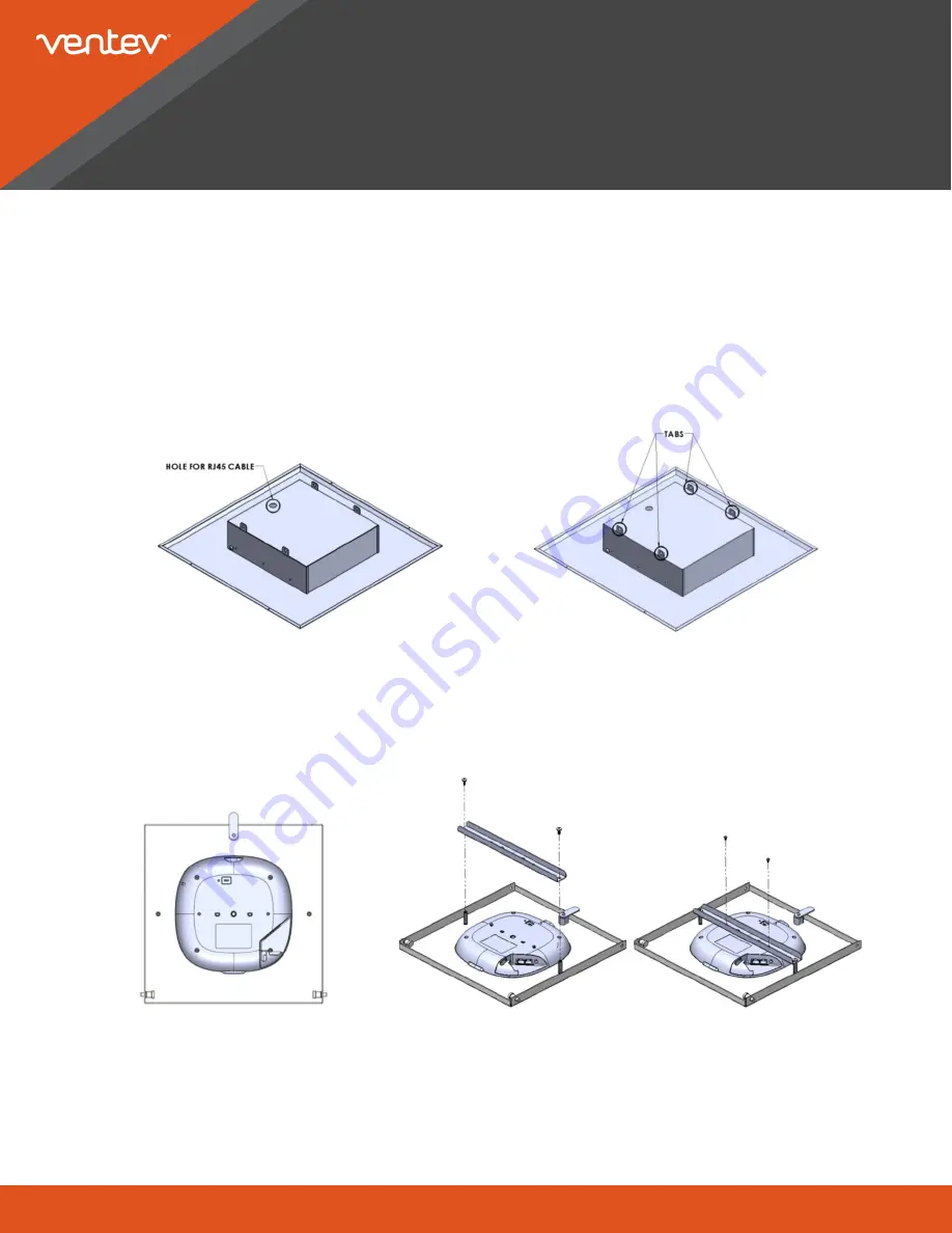
1) Prior to installation, note the knockout hole provided for the RJ45 cable. Refer to Figure 1. A cord grip is supplied
to protect and hold the RJ45 cable.
2) Prepare the ceiling tile grid for a 2’ x 2’ installation. If a 2’ x 4’ ceiling tile is being replaced, follow steps below,
otherwise go to Step 3.
a) Cut existing 2’ x 4’ tile in half
b) Install T-bar provided to create a 2’x2’ opening
c) Install the cut standard tile on one side and the enclosure base on the other side.
www.ventev.com/infra
800.851.4965
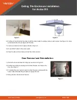
Ceiling Tile Enclosure Installation
for Aruba 515
Instructions for Installation
CAUTION:
Refer to local building codes to determine if additional support is required. Tabs are provided on the
enclosure (see Figure 2) to secure to the building structure.
3) Insert RJ45 cable through the cord grip in the knock-out hole. Cable will be connected after the door is installed
onto the enclosure.
Figure 1.
Figure 2.
Figure 3.
4) Place the Access Point on a surface with the bottom facing upwards. Align the door above the Access Point with
the door hinges facing the AP USB port. Place the door on top of the Access Point. See Figure 3.
5) Fasten the mounting bracket to the door using QTY 2 screws. Secure the Access Point to the mounting bracket
using the QTY 2 screws provided with the Access Point. See Figure 4.
Figure 4.


