background image

HFp Antenna User’s Guide


Page 5  

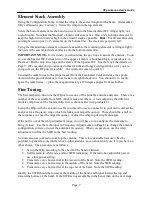
Assembling the Antenna for Use 

1)

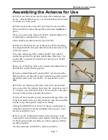
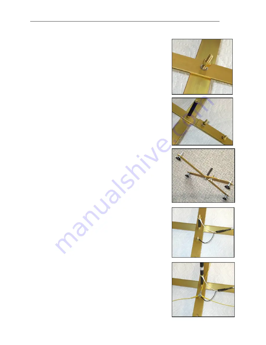
 First, screw the four feet into the ends of the aluminum base 

pieces.  After the HFp is set up, you can adjust these feet to make 
it vertical, so it looks good.   
 

2)

 Place a lock washer on an IEC, and, from the top, insert the 

IEC stud with the washer through the center holes in 

both

 base 

plates.   


Place a wing nut on the bottom of the IEC, align the plates to be 
at right angles, and tighten the wing nut. 


Screw the Base Insulator onto the top of the IEC.  
 

3)

 Place the Wrench on the top of the plate, with the mounting 

hole aligned with the hole just offset from the center hole in one 
of the base pieces.   


Put a lock washer on an IEC, and put the IEC stud with the 
washer through the Wrench hole and the Base Plate hole.  Use 
another IEC to position the wrench slot correctly over the IEC 
removal hole.   
 

4)

 Use one of the Wing Nuts on the bottom of the Base Plate to 

hold the IEC and Wrench in position.   
 

5)

 Screw an Inter-Element Connector (IEC) into the top of the 

Base Insulator, and place the center conductor lug of the coaxial 
pigtail (the white wire) over the IEC.  (Under the IEC is also 
OK)  
 

6)

 Put the coax shield lug (the black wire) on the ground stud, 

put on one of the flat washers, then screw the wing nut on top of 
it - not tight - you will need to take it off in a minute. Then place 
the base on the ground or another flat surface.  
 

7)

 Take off the Ground Lug wing nut and put the lugs from each 

of the three radial wires over the ground lug, then the second flat 
washer on top, them put the wing nut on loosely. 


Arrange the Radial Wires at about 120 degree equally-spaced   
triangular pattern from the lug and tighten the wing nut.  Leave 
the wires spooled for now. 
 

8)

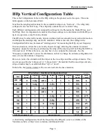
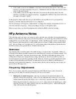
 Next, use the Configuration Table on the next page, or the 

Laminated Card to determine which radiator elements you need 
for the frequency band on which you wish to operate, and their 
assembly sequence. 

Get these elements, and the IECs, ready to assemble. 

Summary of Contents for HFp Vertical

Page 1: ...HFp Antenna User s Guide User s Guide 7 MHz 54 MHz Amateur Radio Antenna HFp Vertical entenna The Ventenna Co LLC P O Box 227 Huston ID 83630 www ventenna com...

Page 2: ...nts 8 HFp Radials 9 Guy Lines 9 The HFp Wrench 10 HFp Hints and Kinks 11 Element Inserts and IECs 11 Waterproofing the Pigtail 11 SWR Standing Wave Ratio 11 Loose Element Inserts 12 HFp V Options 12 H...

Page 3: ...ts marked for example 2 stripe up If you assemble these elements in the wrong orientation the antenna will not tune to the desired frequency The one stripe and zero stripe elements have no orientation...

Page 4: ...tem Description Quantity Zero stripe element 1 Base Plate 2 One stripe element 3 Base Feet 4 Two stripe element 1 Coaxial Pigtail 1 Three stripe element 1 Radial Wire Spool 3 Collapsible Whip 1 Guy Li...

Page 5: ...s on the bottom of the Base Plate to hold the IEC and Wrench in position 5 Screw an Inter Element Connector IEC into the top of the Base Insulator and place the center conductor lug of the coaxial pig...

Page 6: ...ly lowering it shortening the whip all the way may still not bring the SWR to its lowest level If this is the case you may have to re configure the elements See the Frequency Adjustments section for i...

Page 7: ...the HFp is to use one of the portable antenna analyzers There are a number of these available from MFJ AEA Autek and others A list comparing the different models and prices can be found at http www e...

Page 8: ...f you find interesting configurations please email us and tell us about your experiments at info ventenna com Antennas Any antenna truly worth the name will exhibit as large a capture area as possible...

Page 9: ...em to see what effect more radials might have You can also affect the performance of your antenna by lengthening or shortening the tuned radials Change all the radials the same amount a little at a ti...

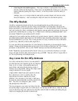
Page 10: ...ry easily toward the antenna tensioning the guy line To loosen the slider grasp and hold the guy line on the antenna side of the slider turn the slider slightly with your other hand and slide it towar...

Page 11: ...er sent to the antenna is being reflected back to the transmitter and not being used by the antenna Most modern transmitters will operate with full power into a load with an SWR of 2 1 or less If the...

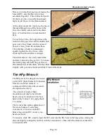
Page 12: ...e plates a large and a small Clamp a Mobile Mount Adapter Magnetic Feet a Back Pack Mount and a Ground Mount Stake The HFp Mounting Accessories flyer in the Manuals section of the website gives detail...

Reviews: