


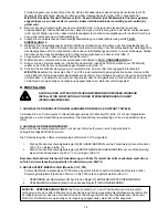


IMPORTANT:
Please note that the T and HT incorporate a switch on delay, which will start the fan after 2
minutes for the set timeout period. The delay is only activated via the LS and not via the pull-cord or humidity
sensor (if applicable). If the LS is switched off during the 2 minute period, the fan will remain off.
B.
SETUP
WARNING: THE FAN AND ANCILLARY CONTROL EQUIPMENT MUST BE ISOLATED FROM
THE POWER SUPPLY DURING THE INSTALLATION / OR MAINTENANCE.
1. SELECTING THE CONSTANT TRICKLE OPTION
Link the Trickle Jumper [TR]
(fig. 12.)
using the supplied Jumper Header to select Constant Trickle. The Trickle
speed option is factory set in the off position (jumper open).
2. SELECTING THE SPEED
This will determine the speed at which the fan will run when activated by either the Pull-cord/LS line/Humidity/PIR.
The speed is factory set at 60m3/h.
1. Turn the Speed Adjuster [S] CLOCKWISE to INCREASE speed up to a maximum of 100m3/h
(fig. 13.).
1. Turn the Speed Adjuster [S] ANTI-CLOCKWISE to decrease speed down to a minimum of 60m3/h
(fig. 13.).
Please note that on the highest speed setting (100m3/h), the fan may consume significantly more power of
the factory set speed (60m3/h).
3. TIMER ADJUSTMENT (T, HT, TM models)
The overrun time period is factory set to 15 minutes. The overrun time period may be adjusted from 5-30
minutes by altering the adjuster on the control PCB [T]
(fig. 13.).
i.
To REDUCE the operating time, turn the adjuster [T] ANTI-CLOCKWISE.
ii.
To INCREASE the operating time, turn the adjuster [T] CLOCKWISE.
IMPORTANT – DELAY TIMER:
The timer function also incorporates a
switch on delay
, which will start the
fan after 2 minutes for the set timeout period. The delay is only activated via the LS and not via the pull-cord or
humidity sensor (if applicable). If the LS is switched off during the 2 minute period, the fan will remain off.
4. HUMIDITY ADJUSTMENT (HT model)
The fan’s Humidity Set-Point is factory set to switch the fan on at 72%RH
(fig. 13.)
.
i.
To LOWER the Set-Point, turn the Humidity Adjuster [RH] ANTI-CLOCKWISE. This makes the fan more
sensitive to RH%, i.e. the fan will come on at a lower RH%.
ii.
To RAISE the Set-Point, turn the Humidity Adjuster [RH] CLOCKWISE. This makes the fan less sensitive
to RH%, i.e. the fan will come on at a higher RH%.
C. WIRING.
WARNING: THE FAN AND ANCILLARY CONTROL EQUIPMENT MUST BE ISOLATED FROM
THE POWER SUPPLY DURING THE INSTALLATION / OR MAINTENANCE.
Use 0.75mm
2
cable
1. Select and follow the appropriate wiring diagram (
fig. 14-15.
).
2. It maybe necessary to feed the mains cable around between the outside of the Base Housing [C] and the Skirt
[H] to prevent the cable from being trapped.
3. Check all connections have been made correctly and ensure all terminal connections and cable clamps are
securely fastened.
4. Ensure the impeller rotates and is free from obstructions.
5
Summary of Contents for SOLO Plus
Page 2: ...2...
Page 22: ...Fig 2 Abb 2 Fig 4 Abb 4 Fig 3 Abb 3 Fig 5 Abb 5 G F E C A Fig 1 Abb 1 H D B 22...
Page 26: ...26...