


4
GENERAL WIRING INSTRUCTIONS
WARNING – THE FAN AND ANY ANCILLARY CONTROL EQUIPMENT MUST BE
ISOLATED FROM THE POWER SUPPLY DURING INSTALLATION AND/OR
MAINTENANCE. THE EQUIPMENT MUST BE EARTHED.
1.
All electrical connections should be made by a properly qualified electrician.
2.
All wiring and connections must be carried out in accordance with current
regulations.
3.
To comply with safety standards, an all pole isolator switch with a contact gap of
at least 3mm must be fitted adjacent to the fan.
4.
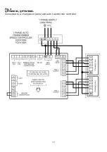
Remove the lid of the QPTW to expose the supply connection terminal blocks
adjacent to the grommets in the wall of the QPTW.
5.
The thermal protection device fitted is an automatic resetting type which must
always be included in the circuit. For ducted applications a manual reset is
required, an ancillary circuit will be required with the TK switch connected into the
circuit. See page 6 for instructions.
6.
Connect the power supply from the local isolator (via any appropriate controls if
fitted) to the terminal blocks via the supplied cable gland using between 4.0mm
and 7.0mm diameter cable. Refer to the wiring diagrams and select the
appropriate connections for the fan, controller or other devices as being installed.
If in doubt please ask.
7.
CAUTION
: In order to avoid a hazard due to inadvertent resetting of the thermal
cut-out, this appliance must not be supplied through an external switching device,
such as a timer, or connected to a circuit that is regularly switched on and off by
the utility.
8.
Ensure that all earth connections have been made.
9.
After making connections to the terminal blocks, replace QPTW lid. Also ensure
that all cable gland nuts, grommets etc. have been used correctly to prevent the
ingress of water.
Fig. 2: Repositioning of shutter assembly.