


A. INSTALLATION
SITING THE CONTROLLER
1.
The controller must not be installed in a shower cubicle or enclosure. It must be sited
away from direct sources of water spray and out of reach (1.5m) of a person using a
fixed bath or shower.
2.
Site away from direct sources of heat. Ambient temperature range 0 to 40ºC. Do not
site in an area containing excessive levels of grease.
3.
Decide where to site the controller and fan (see section siting the fan), and work out the
required cable runs.
SITING THE FAN
1.
The electrical supply to this fan is 12V DC SELV from the mains controller. This means
that the fan may be installed within reach of a person using a fixed bath or shower, i.e.
in a nearby wall. However, the fan must not be placed where it could be submerged in
water or regularly exposed to direct water spray, e.g. from a shower head whether
permanently fixed or movable.
2.
Site away from direct sources of heat. Ambient temperature range 0 to 40ºC. Do not
site in an area containing excessive levels of grease.
3.
If the fan is installed in a room containing a fuel burning appliance the installer must
ensure that air replacement is adequate for both the fan and the fuel burning appliance.
If the fan is used to supply air into the room the installer must ensure that the fan intake
is located at least 600mm Away from any flue outlet.
4.
Ducted Applications. These fans can be used with short lengths of rigid ducting, but
check details first with your Vent-Axia sales centre. Where an excessive amount of
moisture is present in the air, a condensation trap will need to be installed in the
exhaust duct. Horizontal ducts should slope away from the fan unit. Ducts passing
through an unheated roof void should be insulated.
5.
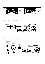
A short circuit of the airflow should always be avoided by siting the fan as far away as
possible from and opposite to the main source of air replacement. FIG.1
PANEL/CEILING MOUNTING
IMPORTANT:
The fan should be installed into a closed duct system or protected by an
exterior air grille.
1.
Cut a 105mm diameter hole in the fixing surface.
2.
Remove the grille by loosening the screw at the bottom of the grille.
3.
Mark the screw centres through the holes in the fan back plate. Drill, plug and screw
into position.
4.
Securely attach ducting.
5.
Replace grille and tighten the screw.
WALL MOUNTING (Wall kit not supplied – see Accessories above)
1.
Cut a 115mm diameter hole through the wall and insert the wall sleeve with the large
diameter sleeve on the outside. Slope the sleeve slightly downwards away from the
fan. Cement both ends into position flush with the wall faces.
2.
Remove the grille by loosening the screw at the bottom of the grille.
3.
Mark the screw centres on the wall through the holes of the fan back plate. Drill plug
and screw into position.
4.
Repeat for the external grille sub-frame. Fix exterior grille into position with the louvres
positioned downwards.
AFTER INSTALLATION ENSURE IMPELLER ROTATES FREELY