


3
B. INSTALLATION
The Lo-CARBON POZIDRY COMPACT can be wall-mounted using the bracket and fixings supplied. A paper
template is also supplied.
The wall should have sufficient strength to support the unit.
Take into consideration the routing of the cable and the ducting that must be fitted to both the inlet and discharge
spigots.
The unit must always be mounted on a vertical wall with the spigots nearest the top of the unit, with a horizontal
airflow.
PLEASE LOCATE THE SEPARATELY BAGGED FILTER!
Wall-mounting
Take off the white plastic cover by removing the 4 screws at the sides.
Take off the metal front cover by removing the 4 screws.
Carefully remove the round to rectangular duct adaptor, packed loosely in the filter plenum (internal, near to the
white plastic spigot). The filter is bagged separately to the unit.
Handing
The Lo-CARBON POZIDRY COMPACT is supplied with the airflow direction horizontally from right to left. If the
opposing airflow is required (left to right), the following should be carried out:
Re-position the cable gland by first loosening off the gland to allow the cable to be pulled through back into the unit.
Swap the cable gland and the blanking plug over to each others’ positions.
Re-secure the cable through the cable gland.
Take off the rear metal cover by removing the 4 screws, and re-fix to the other side of the unit in place of the metal
front cover.
Carefully cut out the skinned area on the white plastic cover where the cable gland will now lie.
Rear-entry inlet
If rear-entry inlet duct connection is required, the appropriate blanking plate (closest to the white plastic inlet spigot),
should be changed over with the white plastic inlet spigot/seal.
The paper template supplied indicates rear entry spigot centres in relation to the fixing hole centres.
Either handing:-
Use the paper template to mark the required fixing-hole positions for the bracket and unit on the wall.
Drill the wall and fit suitable wall plugs to all four positions.
Using 2 suitable size screws fit the mounting bracket to the wall.
Offer the unit up to the wall and allow the mating part on the unit to sit inside the mounting bracket, and then secure
the unit to the wall with suitable size screws through the 2 key-way holes on the back-plate of the unit.
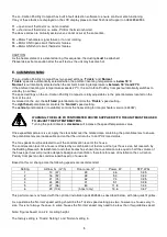
Fit the separately bagged filter using the diagram below to ensure that it is fitted to suit the relevant handing/inlet
spigot position. There are guides in the filter plenum to allow fitting of the filter in two directions. The diagram below
shows the four possible airflow/inlet spigot arrangement options. The arrow shows the airflow direction. The diagonal
line behind the tail of the arrow shows which direction to slide the filter in.
VIEW FROM THE TOP OF THE UNIT
Re-fix the metal front cover.
Following commissioning, re-fix the white plastic cover.