Vent-Axia Lo-Carbon MULTIVENT MVDC-MS Installation And Wiring Instructions Download Page 6


D. WIRING 


WARNING: THE MULTIVENT AND ANCILLARY CONTROL EQUIPMENT MUST BE ISOLATED 
FROM THE POWER SUPPLY DURING THE INSTALLATION / OR MAINTENANCE. 


THE MULTIVENT UNIT MUST BE EARTHED. 


A. MVDC-MS (437634B): 

 
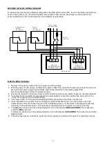
1.  Remove the cover by undoing the four screws and lifting it away. 
2.  With the power off, connect a suitable mains power cable from a switched, fused spur to the power supply PCB. 

Use the cable clamps and clip provided to secure the lead. 

3.  Ensure all connections are correct and that all terminal screws and cable clamps are securely fastened. 
4.  To enable the fan to switch to boost or purge speed when a light is turned on, connect the switched live 

connection from the lighting circuit to one of the LS connections on the mother board. 

5.  The switched live output (230V) from any other switch or controller (such as a pullcord or push button switch, 

humidistat or PIR detector) can be connected to the LS terminal instead of connecting to a lighting circuit. 

6.  Following these set-up instructions, switch the mains supply on and check the system is operating correctly. 


MVDC-MS (437634B) CONNECTION DIAGRAM  


Summary of Contents for Lo-Carbon MULTIVENT MVDC-MS

Page 1: ...CONJUNCTION WITH THE ILLUSTRATIONS PLEASE SAVE THESE INSTRUCTIONS Lo Carbon MULTIVENT MVDC MS MVDC MS H VENTILATION SYSTEMS Stock Ref N MVDC MS 437634B MVDC MS H 443298A Installation and Wiring Instr...

Page 2: ...2...

Page 3: ...should be provided with a 3A fused isolator switch capable of disconnecting all poles having a contact separation of at least 3mm 4 Ensure that the mains supply voltage frequency and phase complies wi...

Page 4: ...y sensor uses one of the two available LS inputs the other remaining LS input can be used to switch the unit to Purge speed The MVDC MS H has the option to switch from Normal to Boost speed in effect...

Page 5: ...ct diameter The larger the better Avoid having any bends filters or other obstructions within 250mm of the fan inlets and outlet 1 Position the MULTIVENT taking into consideration the position of the...

Page 6: ...onnections are correct and that all terminal screws and cable clamps are securely fastened 4 To enable the fan to switch to boost or purge speed when a light is turned on connect the switched live con...

Page 7: ...o the Purge LS connection on the mother board 5 The output 230V from the internal humidistat PCB is connected to the Boost LS terminal 6 Upon installation it is possible that the humidity controller w...

Page 8: ...an isolated switched live connection to the LS connection on the power supply terminal block WARNING THE SWITCHED LIVE CONNECTION TO THE LS CONNECTION MUST BE ISOLATED FOR EXAMPLE USING AN ISOLATOR RE...

Page 9: ...o achieve the stated energy efficiency rating with Local Demand Control LDC the arrangement below should be used The sensors S1 and S2 can be chosen based on the installation requirements Fuse L N E 1...

Page 10: ...clockwise will increase the speed If a purge switch is installed this activates the unit at maximum speed Once the MVDC MS is commissioned apply white label over marked area containing Boost and Norm...

Page 11: ...cal Demand Control Local Demand Control Declared Max Internal External Leakage Rates for BVUs or carry over for regenerative heat exchangers only Ext Leakage Rates for Ducted UVUs 5 Internal 5 Externa...

Page 12: ...fied or repaired by any person not authorised by the company IF CLAIMING UNDER TERMS OF GUARANTEE Please return the complete product carriage paid to your original supplier or nearest Vent Axia Centre...

Reviews: