Vent-Axia Lo-Carbon Centra Series Installation And Wiring Instructions Download Page 5


1  2

ON

1  2

ON

 
Trickle speed selection (6l/s or 9l/s) – (Fig. 6) 

The fan can extract at 6l/s (22m

3

/h) or 9l/s (32m

3

/h) flow rate. 

The fan will boost to 15l/s (54m

3

/h) when the LS connection is  

switched.  

  Factory set at 

6l/s

 (22m

3

/h).  

  Remove jumper connector (JP1) if 

9l/s

 (32m

3

/h)  

extract flow rate is required. 
 

BOOST SPEED SELECTION (Fig. 6):


The fan has two boost speed settings for different installation 
requirements: 
 

1) 

Max speed: Dip switch 2 in the ‘OFF’ position.  


2) 

15 l/s speed: Dip switch 2 should be in the ‘ON’ position.  
(Factory set) 


Dip switch 1 should be in the ‘ON’ position for constant trickle mode or ‘OFF’ for use as an 
intermittent fan. In this mode the fan will only run when the pullcord or LS is activated.  


Boost Timer Setting  

With jumper JP2 removed the fan will enter boost when the LS connection is switched. The fan 
can continue to boost for 15 minutes after the LS connection is switched off. With jumper JP2 in 
place there will be no overrun timer, when the LS connection is switched off the fan will leave 
boost.  

Pullcord (TP & HTP):- 

The integral pullcord activates the timer.  The fan will boost for 15(JP2 

off) or 5(JP2 on) minutes.  If the integral pullcord is pulled for a second time (Once activated), the 
timer will be cancelled and the fan will revert back to the trickle extract rate. 
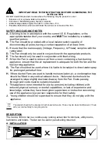
(Fig.3)


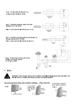
TIMER ADJUSTMENT (T AND TP MODELS) (FIG. 6) 

BEFORE ADJUSTING THE TIMER, SWITCH OFF THE MAINS SUPPLY. TIMER 
SHOULD ONLY BE ADJUSTED BEFORE OR DURING INSTALLATION. 

1. Remove the fan grille. The controller is factory set at 15 minutes approx. 
The overrun time period can be adjusted from 1-30 minutes by altering the 
adjuster on the control PCB. 
2. To REDUCE the operating time, use a small screwdriver to turn the adjuster 

Fig.6. ANTI-CLOCKWISE

3. To INCREASE the operating time, use a small screwdriver to turn the 
adjuster 

Fig.6. CLOCKWISE.


4. Replace the fan grille. 


Timer 
adjustment 
(T & TP) 
OR 
Humidity 
adjustment 
(HT & HTP) 

Fig.6

JP1 

DIP SWITCHES 

JP2 

Summary of Contents for Lo-Carbon Centra Series

Page 1: ...B Lo Carbon Centra T 442955B Lo Carbon Centra HT 447127B Lo Carbon Centra TP 443045B Lo Carbon Centra HTP PLEASE READ INSTRUCTIONS IN CONJUNCTION WITH ILLUSTRATIONS PLEASE SAVE THESE INSTRUCTIONS Lo C...

Page 2: ...iance ensure that the air replacement is adequate for both the fan and the fuel burning appliance G The Fan should not be used where it is liable to be subject to direct water spray for prolonged peri...

Page 3: ...aces 2 Loosen the screw in the bottom of the grille and remove the front grille Mark the screw centres through the holes in the fan back plate Drill plug and screw into position 3 Fix exterior grille...

Page 4: ...lity via remote switch T TP HT HTP Fig 1 Continuous trickle with no remote boost facility T TP 2 Pull grille slightly away from bottom edge 3 Push grille upwards until clear from the fan chassis 1 Loo...

Page 5: ...connection is switched off With jumper JP2 in place there will be no overrun timer when the LS connection is switched off the fan will leave boost Pullcord TP HTP The integral pullcord activates the...

Page 6: ...t face with a damp cloth until clean The fan has sealed for life bearings which do not require lubrication DATA LOGGER The fan records the number of days it has been running for In order to use this f...

Page 7: ...l Factor CTRL 0 95 0 95 0 65 0 65 Control Typology Clock Control Clock Control Local Demand Control Local Demand Control Declared Max Internal External Leakage Rates for BVUs or carry over for regener...

Page 8: ...not been modified or repaired by any person not authorised by the company IF CLAIMING UNDER TERMS OF GUARANTEE Please return the complete product carriage paid to your original supplier or nearest Ve...

Reviews: