Vent-Axia HR300RW6 Operating, Installation And Servicing Instructions Download Page 9

5.0 Maintenance

9

5.1

Cleaning the Unit

1. To ensure optimum performance, the unit

should be inspected every 6 months for build up

of dust or debri and washed every 12 months or

at periods determined by the level of

contamination experienced and according to the

following procedure.

2. Isolate the mains power supply.

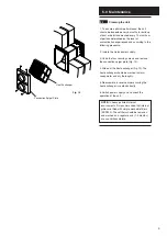
3. Undo the four securing screws and remove

the connection spigot plate (Fig. 10).

4. Slide out the heat exchanger (Fig 10). The

heat exchanger should be washed in warm

soapy water and dry thoroughly.

5. Reassemble in reverse order ensuring the

heat exchanger is seated correctly.

6. Switch power supply on and check the

operation of the unit.

NOTE:

In heavy polluted internal

environments it is recommended that internal

grilles are fitted with simple washable filters

(ESG150). These filters should be removed

and washed on a regular basis (1-3 months)

or as conditions dictate.

Fig. 10

Heat Exchanger

Connection Spigot Plate

Summary of Contents for HR300RW6

Page 1: ...HR300RW6 Semi Remote Wall Mounted Heat Recovery Ventilator Installation and Servicing Instructions Please leave these instructions with the user...

Page 2: ...2...

Page 3: ...3 1 0 Introduction 4 2 0 Site Requirements 5 3 0 Installation 6 4 0 Electrical 8 5 0 Maintenance 9 Section Page Contents...

Page 4: ...esh intake airflow This provides up to 70 heat recovery from the stale extracted air 1 2 Ancillary Equipment 1 The HR300RW6 unit can be used in conjunction with a range of ancillary equipment Controll...

Page 5: ...xceed 40 C 8 Do not site the appliance in the vicinity of excessive levels of airborne oil or grease 9 If the unit is installed in a room containing a fuel burning appliance the installer must ensure...

Page 6: ...controllers and work out the cable runs WARNING Before deciding on the final position for the unit check there are no buried cables pipes or obstructions on the outside wall Cable requirements Suitabl...

Page 7: ...lace with the two fixing screws provided NOTE Ensure the fixings DO NOT inhibit removal or replacement of the heat exchanger 5 Make good around the case 6 Fit the bezel on the inside to cover the maki...

Page 8: ...cket and connect incoming wires to the appropriate terminals Figs 7 8 4 Replace plug into socket 5 Slide the heat exchanger into the unit Fig 9 6 Locate the connection spigot plate on to the front of...

Page 9: ...connection spigot plate Fig 10 4 Slide out the heat exchanger Fig 10 The heat exchanger should be washed in warm soapy water and dry thoroughly 5 Reassemble in reverse order ensuring the heat exchang...

Page 10: ...6 0 Notes 10...

Page 11: ...11...

Page 12: ...Vent Axia Ltd Fleming Way Crawley West Sussex RH10 9YX www vent axia com Comp No 372561 Iss B 0405...

Reviews: