


3.0 Installation
6
3.1
Controllers
1. The
HR
300RW6 unit can be installed in
conjunction with a number of controllers.
VCON6:
The VCON6 controller can be used to
provide Off/Low/Normal/Boost/Sensor control.
(The HS6 humidistat or TIM2 over-run timer can
be used in conjunction with the VCON6 controller
to provide automatic control.
VCON5:
The VCON5 controller can be used to
provide variable speed control.
HS6:
The HS6 is a humidity sensor for switching
between HIGH and LOW speeds during the
daytime according to relative humidity levels.
TIM2:
The TIM2 is an overrun timer which can
also be used to control the
HR
100 unit via a light
switch or remote sensor e.g. PIR detector.
3.2
Initial Preparation
1. Select an approved electrical control
arrangement for the
HR
300RW6 unit (above).
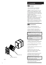
2. After considering the site requirements
(Section 2.0), select a suitable site for the unit
and controllers and work out the cable runs.
WARNING:
Before deciding on the final position
for the unit, check there are no buried cables,
pipes or obstructions on the outside wall.
Cable requirements:
Suitably (Basec or Har)
approved three core cable of appropriate current
carrying capacity.
3. Install the cable runs and appropriate
controllers in conjunction with a fused connection
unit. Contact gap must not be less than 3mm.
4. Choose suitable locations and install internal
louvre grilles into desired locations.
5. Connect ducting to louvre grilles and run to the
desired location of unit.
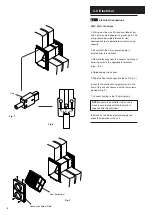
4. Working from the inside, mark out the
position of the mounting hole - 280mm wide x
380mm high (see Fixing Template).
5. Carefully cut the holes in the inner and outer
brick courses to form a suitable aperture to
receive the unit. Ensure that this is level.
NOTE:
Bricks will cut more easily and
accurately if a series of holes are drilled close
together along the marked lines.
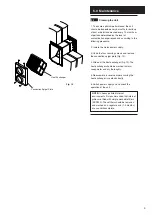
6. Remove the connection spigot plate, heat
exchanger, from the unit (Fig. 4).
Heat Exchanger
Fig. 4
Connection Spigot Plate