2019.10
4 / 31
1. INTRODUCTION
Installation, Operation and Maintenance Instruction concerns heat recovery units manufactured by VENCO. It
consists of basic information and recommendation concerning the design, technical specifications, installation,
operation and maintenance of the heat recovery unit which shall be obeyed to ensure proper fail-safe operation
of the unit. The key to proper and safe operating of the unit, read thoroughly this instruction, use the unit
according to guidelines given in it and follow all safety requirements. The instruction should always be in
proximity of the unit and within easy reach of the service technician.
2. HEAT RECOVERY UNITS and VHR MODELS
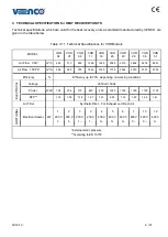
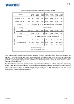
VENCO Standard Heat Recovery Devices are classified in 10 different models; VHR 04 - 07 - 09 - 11 - 16 -
20 - 23 - 29 - 36 - 51. High efficiency EC fan devices are classified in 7 different models; VHR 04 EC - 09 EC
- 11 EC - 16 EC - 29 EC - 36 EC - 51 EC. In all models, the body is made of galvanized sheet and the cabin
is fully insulated for sound and heat insulation. The surface of the unit is polished with electrostatic RAL
colors. All models have two access doors for service to clean and exhaust air filters.
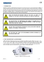
Figure 2.1. VENCO Heat Recovery Units
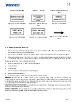
READ THE INSTRUCTION BEFORE START-UP THE UNIT and KEEP IT IN
PROXIMITY OF THE UNIT and WITHIN EASY REACH OF SERVICE TECHNICIAN.
THE APPLIER WILL BE RESPONSIBLE FOR DEFECTS OCCURED DUE TO
OPERATING THE UNIT BY NOT AUTHORIZED PERSONEL or USING THE SPARE
PARTS WHICH ARE NOT ORIGINAL.
THE UNIT MUST BE OPERATED APPROPRIATE APPLICATIONS FOR PURPOSES
DESIGN and TECHNICAL SPECIFICATIONS
THE UNIT MUST NOT USED IN THE ENVIROMENTS WHERE CORROSION and
EXPLOSIVE GASSES EXIST
Summary of Contents for VHR 04
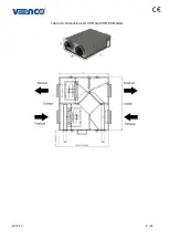
Page 8: ...2019 10 8 31 Table 3 2 Dimensions for VHR and VHR EC Models ...
Page 23: ...2019 10 23 31 17 APPENDIX 17 1 APPENDIX 1 Standard Controller SEC Electrical Wiring Diagram ...
Page 24: ...2019 10 24 31 17 2 APPENDIX 2 Functional Controller FEC AC FAN Electrical Wiring Diagram ...
Page 25: ...2019 10 25 31 17 3 APPENDIX 3 Functional Controller FEC EC FAN Electrical Wiring Diagram ...


