


483515 • DFDR FDR FSDR, Rev. 3, January 2022
Copyright 2022 © Venco Products
8
As a result of our commitment to continuous improvement, Venco reserves the right to change specifications
without notice.
Our Commitment
Phone: 1.833.881.0565 • Fax: 715.355.2399 • E-mail: [email protected] • Website: www.vencoproducts.com
Damper Maintenance
Dampers do not typically require maintenance as long as they are kept dry and clean. If cleaning is necessary, use
mild detergents or solvents. If lubrication is desired for components such as axle bearings, jackshaft bearings and
jamb seals, do not use oil-based lubricants or any other lubricants that attract contaminants such as dust.
Dampers and their actuator(s) must be maintained, cycled, and tested a minimum in accordance with:
• The latest editions of NFPA 80, 90A, 92, 101, 105, UL864, AMCA 503-03 and local codes.
• Actuator manufacturer recommendations.
Damper Troubleshooting
The following is a possible cause and correction list for common concerns with dampers.
Symptom
Possible Cause
Corrective Action
Damper does not
fully open and/or
close
Frame is 'racked' causing blades to
bind on jamb seals
Adjust frame such that it is square and plumb
Actuator linkage loose
Close damper, disconnect power, adjust and
tighten linkage
Defective motor
Replace
Screws in damper linkage
Damper installed too far into wall. Move out to
line as designated on damper label
Contaminants on damper
Clean with a non-oil based solvent (see Damper
Maintenance)
RRL or TOR sensor
tripped
Heat
Push reset button located on backside of RRL or
TOR
Damper does not
operate
No power supplied to the actuator
Add power supply
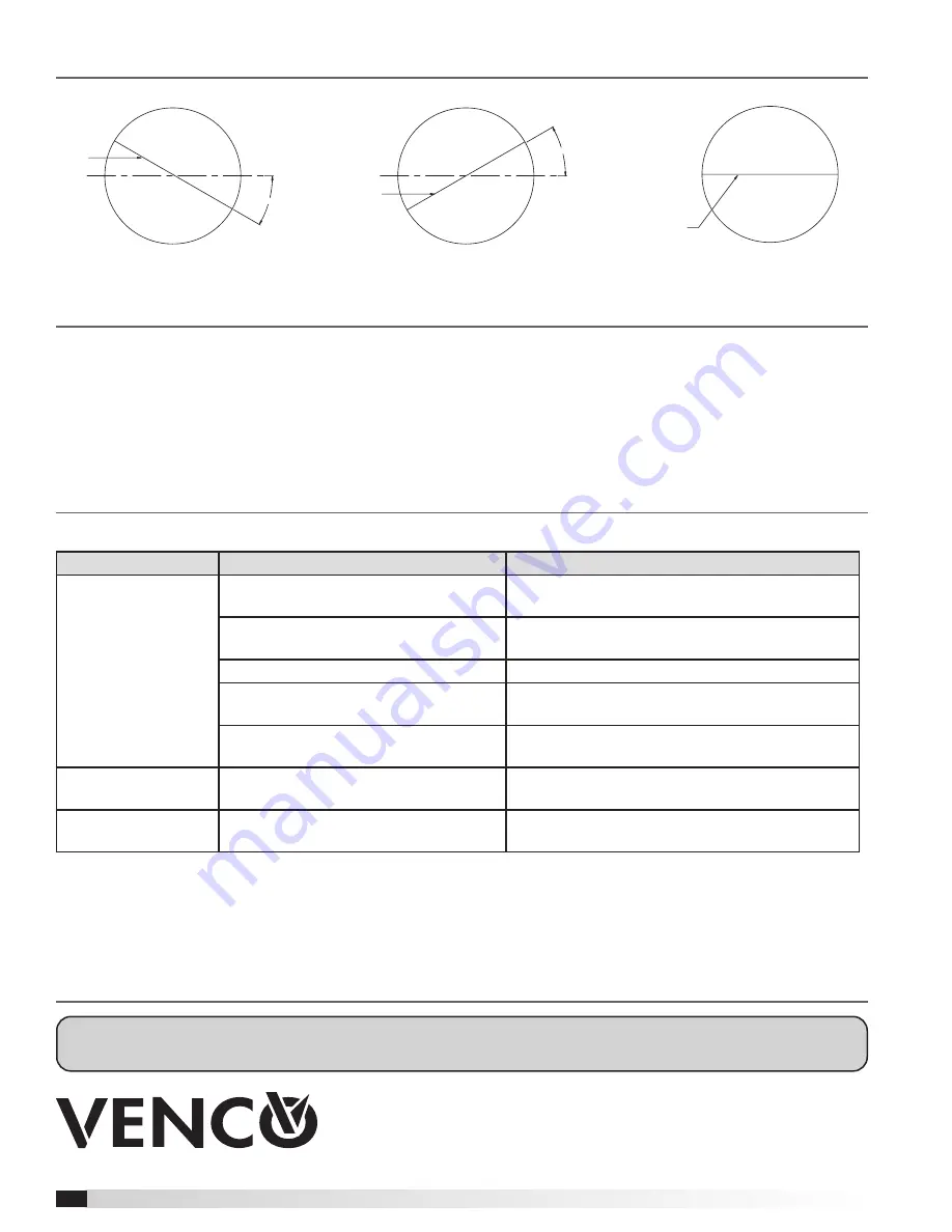
Blade Orientation
Axle
30°
30° Off Horizontal (Maximum)
Axle
30°
30° Off Horizontal (Maximum)
Axle
Normal


