


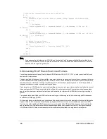


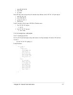

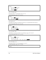

// Perform the interpolation using the timing firing
K = 0;
While (K < 31)
// Determine if you’re in the first or second firing sequence of the data block
if (K < 16)
Then
// Interpolate
Precision_Azimuth[K] := Azimuth[datablock_n] + (AzimuthGap * 2.304 μs * K) /
55.296 μs);
Else
// Interpolate
Precision_Azimuth[K] := Azimuth[datablock_n] + (AzimuthGap * 2.304 μs * ((K-16) +
55.296 μs)) / (2 * 55.296 μs);
Endif
// Adjust for any rollover
If Precision_Azimuth[K] >= 360
Then
Precision_Azimuth[K] := Precision_Azimuth[K] – 360;
Endif
K++;
End While
Note:
If you examine the VeloView code in GITHUB, you’ll notice that VeloView uses a slightly different method to cal-
culate XYZ coordinates. VeloView operates on the azimuth as if it were read as positive in the counter-clockwise
direction with the origin along the X axis.
9.6 Converting PCAP Files to Point Cloud Formats
Converting a packet capture (pcap) file of Velodyne LiDAR data to a LAS, LAZ, XYZ, PLY, or other point cloud file format
can be a non-trivial process.
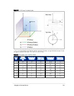
The data provided by the sensor in the pcap file is measured relative to the sensor’s reference frame - the sensor’s internal
three dimensional coordinate system which moves with the sensor. That’s markedly different from a point cloud file where
the data points are referenced to a single coordinate system. That coordinate system might be an earth-frame (latitude,
longitude, elevation) or another convenient reference frame.
Processing the raw LiDAR data into a point cloud is called geo-referencing. In geo-referencing, the user takes into account
the sensor’s position (X/Y/Z) and orientation (pitch/roll/yaw) for each measurement. Knowing these six values enables a
user to perform the proper mathematical rotations and translations to reference the LiDAR data into a single coordinate
system.
Two popular techniques Velodyne LiDAR customers use for geo-referencing are inertial referencing and Simultaneous
Localization and Mapping (SLAM).
With inertial referencing, the location and orientation of the sensor at every moment is recorded with an Inertial Navigation
System (INS). An INS combines a Global Positioning System (GPS) receiver with an Inertial Measurement Unit (IMU).
Data from the both the INS and LiDAR sensor are time-synchronized to the GPS satellite’s reference clock, enabling the
user to match each LiDAR data point with its corresponding position and orientation from the INS. Having matched the
LiDAR data with the INS data, each measurement is mathematically translated into a single coordinate system.
66
VLP-16 User Manual