


109
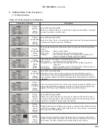
“Press”
System
Setup
button to access the following parameters:
Factory
Setting
Range /
Choices
Parameter and Description
Fahrenheit
Fahrenheit,
Celsius
Temperature Units
The Temperature Units parameter determines whether temperature is represented in units of Fahrenheit
or Celsius degrees.
Wired
Not Installed,
Wired
Wireless
Outdoor Sensor Source
Not Installed Outdoor Sensor is not connected to the boiler, the sensor is not monitored for faults.
Wired Outdoor Sensor is installed directly on the boiler terminal Strip.
Wireless Outdoor sensor is installed and wireless.
0
-100 to 100
tenths of degree
Outdoor Air Sensor Calibration
Outdoor Air Sensor Calibration offset allows a single point calibration. Using a reliable source (reference)
for outdoor temperature measure outdoor air temperature. Set the offset equal to the difference between
the controller reading and the reference. The result will be the Control’s measurement matching the
reference reading.
Enabled
Enable/Disable
Frost Protection
Disable Frost Protection is not used.
Enable Boiler and system circulators start and boiler fires when low outside air, supply and return
temperatures are sensed.
Disabled
Enable/Disable
Warm Weather Shutdown Enable
Disable Warm Weather Shutdown (WWSD) is not used.
Enable The boiler and pumps will not be allowed to start in response to a central heat call for heat if
the outside temperature is greater than the WWSD setpoint. WWSD is initiated as soon as
outside air temperature is above WWSD Setpoint. The control does not require call for heat
to be satisfied. The boiler will still start in response to a Domestic Hot Water call for heat.
70°F
0-100°F
Warm Weather Shutdown Setpoint
The Warm Weather Shutdown (WWSD) Setpoint used to shutdown the boiler when enabled by the
“WWSD Enable” parameter.
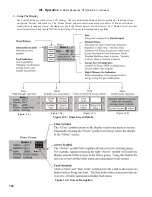
2. Adjusting Parameters (continued)
The following pages describe the Control’s adjustable parameters. Parameters are presented in the order they appear on
the Control’s Display, from top to bottom and, left to right. From the “Home” screen select the Adjust button to access the
adjustment mode screens show below (if required, refer to the previous page to review how to enter Adjustment mode):
XII. Operation
F. Changing Adjustable Parameters (continued)
Summary of Contents for Raptor RPTR085
Page 1: ...1...
Page 13: ...13 Figure 5 1 Wall Layout Mounting Hole Location V Mounting The Boiler continued...
Page 87: ...87 Figure 10 5 Internal Wiring Ladder Diagram X Wiring continued...
Page 88: ...88 X Wiring continued...
Page 97: ...97 Operating Instructions XI Start Up and Checkout continued...
Page 142: ...142 XV Repair Parts continued 3A 3B 3C 3D 3F 3E 3G 3H 3O 3P 3Q 3R 3J 3K 3I 3M 3N 3L All Models...
Page 148: ...148 XV Repair Parts continued 6D 6B 6A 6E 6I 6G 6L 6N 6H 6C 6K 6M 6C 6C 6J 6J 6F All Models...
Page 172: ...172...