background image


13 

Chapter 3


Operation 


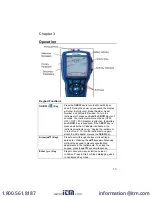
Keypad Functions 

ON/OFF (


) Key  

Press the 

ON/OFF 

key to turn the Model 9565 on 

and off. During the power up sequence the display 

will show the following:  Model Number, Serial 

Number, and Software Revision. To turn the 

instrument off, press and 

hold

 the 

ON/OFF

 Key for 3 

seconds. The instrument will count down (OFF2, 

OFF1, OFF). If AC Adapter is attached, the Battery 

and 

ON/OFF

 Key is bypassed. If the 

ON/OFF

 Key is 

pressed while the AC adapter is attached, the 

instrument instructs you to “Unplug the instrument 

to turn off unit”. To turn the instrument on again, 

attach the AC adapter or press the 

ON/OFF

 Key.  

Arrow (



) Keys 

Press to scroll through choices while setting a 

parameter. Pressing the 



 keys simultaneously 

will lock the keypad to prevent unauthorized 

adjustments to the instruments. To unlock the 

keypad, press the 



 keys simultaneously. 

Enter (

 ) Key 

Press to accept a menu selection, value or 

condition. Press to Start or Stop datalogging when 

in Continuous Key mode. 

www.

.com

[email protected]

1.800.561.8187

Summary of Contents for 9565-P

Page 1: ...VELOCICALC AIR VELOCITY METER MODEL 9565 SERIES OPERATION AND SERVICE MANUAL P N 6004851 REVISION F JUNE 2018 www com information itm com 1 800 561 8187 ...

Page 2: ...www com information itm com 1 800 561 8187 ...

Page 3: ...ler warrants only that the instrument or product is properly calibrated at the time of its manufacture Instruments returned for calibration are not covered by this warranty g This warranty is VOID if the instrument is opened by anyone other than a factory authorized service center with the one exception where requirements set forth in the manual allow an operator to replace consumables or perform ...

Page 4: ...han 12 months after a cause of action has accrued The goods returned under warranty to Seller s factory shall be at Buyer s risk of loss and will be returned if at all at Seller s risk of loss Buyer and all users are deemed to have accepted this LIMITATION OF WARRANTY AND LIABILITY which contains the complete and exclusive limited warranty of Seller This LIMITATION OF WARRANTY AND LIABILITY may no...

Page 5: ...e Probe 8 Connecting an Optional Pitot Probe or Airflow straight pitot Probe 9 Thermocouple Ports 10 Connecting the Thermocouples 10 Connecting the Optional Bluetooth Portable Printer Device Models 9565 P and 9565 X only 11 Connecting to a Computer 11 CHAPTER 3 OPERATION 13 Keypad Functions 13 Common Terms 14 Menus 15 ZERO PRESSURE 15 DISPLAY SETUP 16 SETTINGS 17 FLOW SET UP 17 VOC SETUP 19 ACTUAL...

Page 6: ...oConnects 36 Printing Data Using the Portable Printer Models 9565 P and 9565 X only 36 TrakPro Data Analysis Software 37 LogDat2 Downloading Software 37 CHAPTER 4 MAINTENANCE 39 Recalibration 39 Cases 39 Storage 39 CHAPTER 5 TROUBLESHOOTING 41 APPENDIX A SPECIFICATIONS 43 APPENDIX B OPTIONAL PLUG IN PROBES 47 www com information itm com 1 800 561 8187 ...

Page 7: ...supports the following models Model Description 9565 P Multi Function Ventilation Meter with Differential Pressure Sensor 9565 P NB Multi Function Ventilation Meter with Differential Pressure Sensor No Bluetooth 9565 X Multi Function Ventilation Meter No Differential Pressure Sensor 9565 X NB Multi Function Ventilation Meter No Differential Pressure Sensor No Bluetooth Bluetooth Safety and Complia...

Page 8: ...interference to radio communications However there is no guarantee that interference will not occur in a particular installation If this equipment does cause harmful interference to radio or television reception which can be determined by turning the equipment off and on the user is encouraged to try to correct the interference by one or more of the following measures Reorient or relocate the rece...

Page 9: ... W A R N I N G Changes or modifications not expressly approved by the party responsible for compliance could void the user s authority to operate the equipment www com information itm com 1 800 561 8187 ...

Page 10: ...P switch will need to be changed Refer to the next section DIP Switch Settings Carbon zinc batteries are not recommended because of the danger of battery acid leakage DIP Switch Settings To access the DIP switch remove the batteries from the battery compartment On the inside of the battery compartment there is a window with a single DIP switch see figure below The table below shows the functions f...

Page 11: ...DIP switch in the battery compartment is set to NiMH If the DIP switch is set to Alkaline and the AC power adapter is connected then the batteries will be bypassed and the meter will be powered by the AC adapter Be sure to provide the correct voltage and frequency which is marked on the back of the AC adapter AC Adapter input www com information itm com 1 800 561 8187 ...

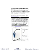
Page 12: ...robe make sure the sensor window is fully exposed and the orientation dimple is facing upstream N O T E For temperature and humidity measurements make sure that at least 3 inches 7 5 cm of the probe is in the flow to allow the temperature and humidity sensors to be in the air stream Extending the Probe To extend the probe hold the handle in one hand while pulling on the probe tip with the other ha...

Page 13: ...ures in ductwork For more information see Application Note TSI 107 Connecting the Static Pressure Probe The Static Pressure probe included with the 9565 P is connected to the port on the 9565 P using the included tubing The Static Pressure probe is used to measure the duct static pressure and features a magnet which holds the probe to the ductwork Negative Pressure Port Positive Pressure Port www ...

Page 14: ...r to Application Note TSI 106 N O T E The pitot velocity needs a valid temperature to perform the standard or actual velocity correction This is accomplished in the Actual Std Setup menu If no probe capable of measuring temperature plug in probe or thermocouple is connected the Temp Source must be set to Entered The duct air temperature must then be manually inputted by the user using the Entered ...

Page 15: ...nnecting the Thermocouples The K Alloy thermocouple with mini connector has one terminal wider than the other The wider terminal will be inserted into the bottom of the TC1 or TC2 connector port Thermocouples from an alternate TSI supplier must have the metal sheath electrically isolated from the wires inside Failure to meet this requirement may result in false readings electrical shock or fire ha...

Page 16: ...on on establishing Bluetooth connections refer to TSI Applications Note TSI 150 Connecting to a Computer Use the Computer Interface USB Cable provided with the Model 9565 to connect the instrument to a computer for downloading stored data C a u t i o n This symbol is used to indicate that the data port of the Model 9565 is not intended for connection to a public telecommunications network Connect ...

Page 17: ... the ON OFF Key is pressed while the AC adapter is attached the instrument instructs you to Unplug the instrument to turn off unit To turn the instrument on again attach the AC adapter or press the ON OFF Key Arrow Keys Press to scroll through choices while setting a parameter Pressing the keys simultaneously will lock the keypad to prevent unauthorized adjustments to the instruments To unlock the...

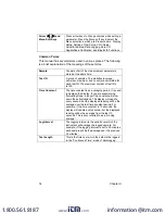
Page 18: ... Constant The time constant is an averaging period It is used to dampen the display If you are experiencing fluctuating flows a longer time constant will slow down those fluctuations The display will update every second but the displayed reading will be the average over the last time constant period For example if the time constant is 10 seconds the display will update every second but the display...

Page 19: ...nstrument on for a minimum of five minutes to let it warm up before zeroing the pressure sensor To zero the pressure reading leave the positive and negative ports open to atmosphere and select the Zero Press The pressure sensor should be zeroed after initial warm up and checked periodically The instrument will indicate if the pressure zero was successful MENU Zero Press Display Setup Settings Flow...

Page 20: ...ependent on the type of probe currently connected When set to PRIMARY measurement will be the large font on the display When set to ON measurement will be displayed as a secondary parameter up to 4 can be displayed When set to OFF measurement will not be displayed N O T E Pitot Velocity and AFProbe Velocity cannot both be ON at the same time nor can one be set to PRIMARY and the other to ON Only o...

Page 21: ...ed type To change the value highlight the Enter Settings option and press the key MENU Zero Press Display Setup Settings Flow Setup VOC Setup Actual Std Setup Data Logging Zero CO Applications Calibration Bluetooth Functions SETTINGS Language English Beeper Disable Select Units Time Constant 1 Second Contrast 5 Set Time 09 14 AM Set Date 10 31 08 Time Format 12 hr Date Format MM DD YY Number Forma...

Page 22: ... are obtained from the diffuser or flow station manufacturer For more information refer to Application Note TSI 114 Up to 5 rectangular ducts 5 round ducts 5 duct areas and 5 Kfactors can be pre programmed for quick use on a jobsite When Flow is set as the Primary measurement in the Display Setup menu the dimensions or Kfactor will also be displayed N O T E For flow measurements with round rectang...

Page 23: ...s follows can be used with this function AM 100 AM 300 AM 600 and AM 1200 If a horn model number is chosen the instrument will return to measuring mode and use a preprogrammed curve to calculate flow rate from velocity when using a thermoanemometer probe The Air cone selection applies to the Model 995 Rotating Vane Anemometer and the Air Cone kit p n 801749 which are used to take flow measurements...

Page 24: ...probe or thermocouple The Entered Temp range is from 40 to 1832 F 40 to 1000 C For more information on Actual and Standard conditions refer to Application Note TSI 109 MENU Zero Press Display Setup Settings Flow Setup VOC Setup Actual Std Setup Data Logging Zero CO Applications Calibration Bluetooth Functions ACTUAL STD SETUP Setting Standard Temp source Entered SETTING Standard Actual TEMP SOURCE...

Page 25: ...an one be set to PRIMARY and the other to ON Only one can be ON at any given time Log Mode Log Settings The 9565 can be programmed to store measurements to memory in several different logging formats Manual Auto save Cont key Cont time Program 1 Program 2 MENU Zero Press Display Setup Settings Flow Setup VOC Setup Actual Std Setup Data Logging Zero CO Applications Calibration Bluetooth Functions D...

Page 26: ...ve Logging In Auto save mode the user samples are automatically logged to memory at the end of the sampling period To start logging press the key DATA LOGGING Measurements Log Mode Manual Log Settings Choose Test Test 001 Name Test View Data Delete Data Memory LOG MODE Manual Auto save Cont key Cont time Program 1 Program 2 DATA LOGGING Measurements Log Mode Auto save Log Settings Choose Test Test...

Page 27: ...ment will continue logging until the key is pressed again DATA LOGGING Measurements Log Mode Auto save Log Settings Choose Test Test 001 Name Test View Data Delete Data Memory SAMPLE TIME 00 05 Min Sec DATA LOGGING Measurements Log Mode Cont key Log Settings Choose Test Test 001 Name Test View Data Delete Data Memory LOG MODE Manual Auto save Cont key Cont time Program 1 Program 2 www com informat...

Page 28: ...t time mode the user starts taking readings by pressing the key The instrument will continue taking samples until the time as set in Test Length has elapsed DATA LOGGING Measurements Log Mode Cont key Log Settings Choose Test Test 001 Name Test View Data Delete Data Memory LOG SETTINGS Log Interval 00 01 LOG INTERVAL 00 05 Min Sec DATA LOGGING Measurements Log Mode Cont time Log Settings Choose Te...

Page 29: ...ttended logging A Lock symbol will appear on the display To unlock the keypad press the keys simultaneously The Lock symbol will disappear DATA LOGGING Measurements Log Mode Cont time Log Settings Choose Test Test 001 Name Test View Data Delete Data Memory LOG SETTINGS Log Interval 00 01 Test Length 00 00 01 LOG INTERVAL 00 05 Min Sec TEST LENGTH 00 00 05 Day Hour Min www com information itm com 1...

Page 30: ...fer to the TrakPro Data Analysis Software User s Guide which can be found on the TrakPro software CD which is included with the 9565 TrakPro is a trademark of TSI Incorporated DATA LOGGING Measurements Log Mode Cont time Log Settings Choose Test Test 001 Name Test View Data Delete Data Memory LOG MODE Manual Auto save Cont key Cont time Program 1 Program 2 www com information itm com 1 800 561 818...

Page 31: ...omizing the Test ID name using 8 characters maximum Use the arrow keys to move the cursor to a desired location press to accept Repeat until the desired name appears Press SAVE to store custom ID name DATA LOGGING Measurements Log Mode Cont time Log Settings Choose Test Test 001 Name Test View Data Delete Data Memory CHOOSE TEST Test 001 9 Samples Test 002 7 Samples Test 003 0 Samples Test 004 0 S...

Page 32: ...gs Choose Test Test 001 Name Test View Data Delete Data Memory VIEW DATA Choose Test Test 001 View Stats View Samples Print Test CHOOSE TEST Test 001 9 Samples Test 002 7 Samples Test 003 0 Samples Test 004 0 Samples Test 005 0 Samples Test 006 0 Samples Test 007 0 Samples Test 008 0 Samples Test 009 0 Samples Test 010 0 Samples DATES DATA LOGGING Measurements Log Mode Auto save Log Settings Choos...

Page 33: ...th communications To use the PRINT command Bluetooth communications must be established between the instrument and the Model 8934 wireless printer or PC set up with Bluetooth communications View Samples TEST 001 Pressure Avg 1 739 in H2O Min 1 665 in H2O Max 1 812 in H2O Samples 9 10 31 08 07 01 39 AM PRINT TEST 001 Temperature Avg 78 2 F Min 78 1 F Max 78 3 F Samples 9 10 31 08 07 01 39 AM PRINT ...

Page 34: ...e established between the instrument and the Model 8934 wireless printer or PC set up with Bluetooth communications For more information on establishing Bluetooth connections refer to TSI Applications Note TSI 150 TEST 001 Velocity Sample 1 218 ft min Sample 2 280 ft min Sample 3 316 ft min Sample 4 399 ft min Sample 5 188 ft min Sample 6 306 ft min Sample 7 313 ft min Sample 8 294 ft min Sample 9...

Page 35: ...w Data Delete Data Memory DELETE DATA Delete All Delete Test Delete Sample DELETE DATA Delete All Delete Test Delete Sample DELETE ALL Are you sure YES NO DELETE DATA Delete All Delete Test Delete Sample DELETE TEST Test 001 14 Samples Test 002 10 Samples Test 003 12 Samples Test 004 8 Samples Test 005 7 Samples Test 006 15 Samples Test 007 0 Samples Test 008 0 Samples Test 009 0 Samples Test 010 ...

Page 36: ...clear memory and reset the memory available to 100 DELETE DATA Delete All Delete Test Delete Sample DELETE SAMPLE Test 001 14 Samples Test 002 10 Samples Test 003 12 Samples Test 004 8 Samples Test 005 7 Samples Test 006 15 Samples Test 007 0 Samples Test 008 0 Samples Test 009 0 Samples Test 010 0 Samples DATES MEMORY Test ID 83 Sample 92 www com information itm com 1 800 561 8187 ...

Page 37: ... that may have drifted Initiating the Zero CO function will show the sensor CO reading and the time remaining N O T E The Zero CO function should be performed in an area where no combustion is taking place which may affect zeroing of the sensor MENU Zero Press Display Setup Settings Flow Setup VOC Setup Actual Std Setup Data Logging Zero CO Applications Calibration Bluetooth Functions ZERO CO 0 0 ...

Page 38: ... refer to the following information Draft Rate Application Note TSI 142 Heat Flow Application Note TSI 124 Turbulence Intensity Application Note TSI 141 Percent Outside Air Application Note TSI 138 Leakage Test PANDA Manual MENU Zero Press Display Setup Settings Flow Setup VOC Setup Actual Std Setup Data Logging Zero CO Applications Calibration Bluetooth Functions APPLICATIONS Draft Rate Heatflow ...

Page 39: ...o assist with wireless connections to other Bluetooth capable devices Discover Devices Start the Bluetooth process of finding other devices from the VelociCalc Model 9565 P or 9565 X MENU Zero Press Display Setup Settings Flow Setup VOC Setup Actual Std Setup Data Logging Zero CO Applications Calibration Bluetooth Functions CALIBRATION Calibrate Temp Calibrate Vel Calibrate RH Calibrate B P Calibr...

Page 40: ...nter AutoConnects Specifies how many times the instrument will attempt to reattach to a paired device after the power is turned on For this option the instrument Discoverability setting must be enabled Settings are 0 to 5 times For more information on establishing Bluetooth connections refer to TSI Applications Note TSI 150 Printing Data Using the Portable Printer Models 9565 P and 9565 X only To ...

Page 41: ... Any USB port can be used LogDat2 Downloading Software The VelociCalc Model 9565 also includes downloading software called LogDat2 LogDat2 software transfers the stored data from the Model 9565 to a computer as a spreadsheet file This software is useful for applications such as duct traverses fume hood and filter face velocity testing To download data from the Model 9565 connect the supplied compu...

Page 42: ... calibration capability For complete multiple point calibration and certification the instrument must be returned to the factory Cases If the instrument case or storage case needs cleaning wipe it off with a soft cloth and isopropyl alcohol or a mild detergent Never immerse the Model 9565 If the enclosure of the Model 9565 or the AC adapter becomes broken it must be replaced immediately to prevent...

Page 43: ...stant No response to keypad Keypad locked out Unlock keypad by pressing keys simultaneously Instrument Error message appears Memory is full Download data if desired then DELETE ALL memory Fault in instrument Factory service required on instrument Probe Error message appears Fault in probe Factory service required on probe Probe is plugged in but the instrument does not recognize it Probe was plugg...

Page 44: ...ow Rate Range Actual range is a function of actual velocity pressure duct size and K factor Temperature TA Probe Range 14 to 140 F 10 to 60 C Accuracy5 0 5 F 0 3 C Resolution 0 1 F 0 1 C Relative Humidity TA Probe Range 5 to 95 RH Accuracy6 3 RH Resolution 0 1 RH Wet Bulb Temperature TA Probe Range 40 to 140 F 5 to 60 C Resolution 0 1 F 0 1 C Dew Point TA Probe Range 5 to 120 F 15 to 49 C Resoluti...

Page 45: ... Storage Capabilities Range 26 500 samples and 100 test IDs one sample can contain fourteen measurement types Logging Interval Intervals 1 second to 1 hour Time Constant Intervals User selectable Response Time Velocity 200 msec Temperature 2 minutes to 66 of final value Pressure 0 1 msec Humidity 1 minute to 66 of final value External Meter Dimensions 3 8 in 8 3 in 2 1 in 9 7 cm 21 1 cm 5 3 cm Met...

Page 46: ...t recommended below 1000 ft min 5 m s and are best suited to velocities over 2000 ft min 10 00 m s Range can vary depending on barometric pressure 4 Accuracy is a function of converting pressure to velocity Conversion accuracy improves when actual pressure values increase 5 Accuracy with instrument case at 77 F 25 C add uncertainty of 0 05 F F 0 03 C C for change in instrument temperature 6 Accura...

Page 47: ...ty Probe Model Description 800220 Temperature and humidity probe Indoor Air Quality IAQ Probes Model Description 980 Indoor Air Quality Probe Temperature Humidity CO2 982 Indoor Air Quality Probe Temperature Humidity CO2 and CO Volatile Organic Compounds VOC Probes Model Description 984 Low Concentration ppb VOC and Temperature 985 High Concentration ppm VOC and Temperature 986 Low Concentration p...

Page 48: ...6 8 mm diameter 634634002 Pitot Probe 24 61 cm 5 16 8 mm diameter 634634003 Pitot Probe 36 91 cm 5 16 8 mm diameter 634634005 Pitot Probe 60 152 cm 5 16 8 mm diameter 634634004 Telescoping Pitot Probe 8 to 38 20 cm to 96 cm 800187 Air Flow Probe Straight Pitot 18 46 cm 5 16 8 mm diameter www com information itm com 1 800 561 8187 ...

Reviews: