


www.velocitydetection.com Doc: GLT-294-7-5 Issue: 001 Date: 05/03/2020
General
The Velocity MMP system network has the facility to monitor, indicate and control the functions of a fire alarm
installation, thus allowing signals to be distributed around a large site. The network will accommodate up to 64
nodes. The network uses RS485 data communication and a total network cable length of up to 10km is possible. All
panels will continue to function in stand-alone mode, even if the network fails. On a Velocity MMP running in a
network, all events are reported at all panels and all panels are able to remotely program other MMP panels sitting
on the network. Operation of outputs over the network is determined by the programmed cause & effects. Any
input on the network can be programmed to operate any output.
Installation
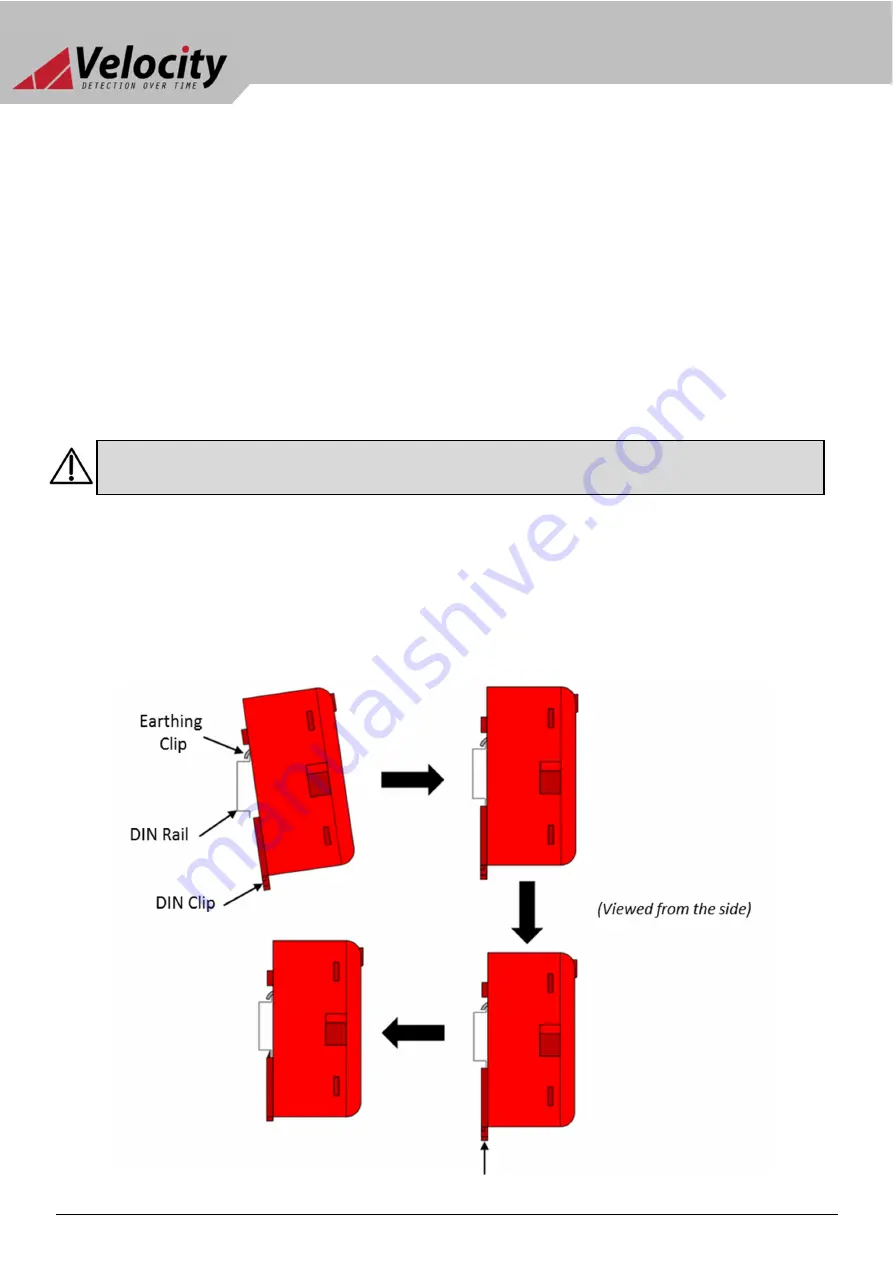
1.
Ensure that the installation area is free from any cables or wires that may get caught, and that there is enough
space on the DIN rail to mount the module. Also ensure that the DIN clip underneath the module is in the open
position.
2.
Place the module onto the DIN rail, hooking the metal earth clip underneath onto the rail first.
3.
Once the earth clip is hooked, push the bottom of the module onto the rail so that the module sits flat.
4.
Push the plastic DIN clip (located at the bottom of the module) upwards to lock and secure the module into
position.
VL-NWM [NETWORK MODULE] Installation Instructions
ATTENTION:
THE PANEL MUST BE POWERED DOWN, AND DISCONNECTED FROM THE BATTERIES BEFORE
INSTALLING OR REMOVING ANY MODULES.