


Appendix M
Advanced Motor Setup
6
The
VXM
applies
energy
to
the
motors
based
on
the
size
of
the
motor.
The
physical
size
is
the
important
aspect
that
determines
the
amount
energy
the
VXM
will
apply.
The
size
of
the
motor
is
proportional
to
the
motor’s
current
times
it’s
inductance.
Motors
of
the
same
current
are
not
the
same
to
the
VXM.
When
using
motors
not
listed
for
use
with
the
VXM,
set
the
VXM
to
motor
setting
that
has
the
same
or
higher
current
times
inductance
value
than
the
motor
you
wish
to
use.
s
et
motor
type/size
selected
for
axis
m
and
applies
100%
power
to
motor
in
jog
mode
(normally
70%
power),
=axis#
(1,2,3,4.)
Value
for
x
should
be
a
number
between
0
and
6.
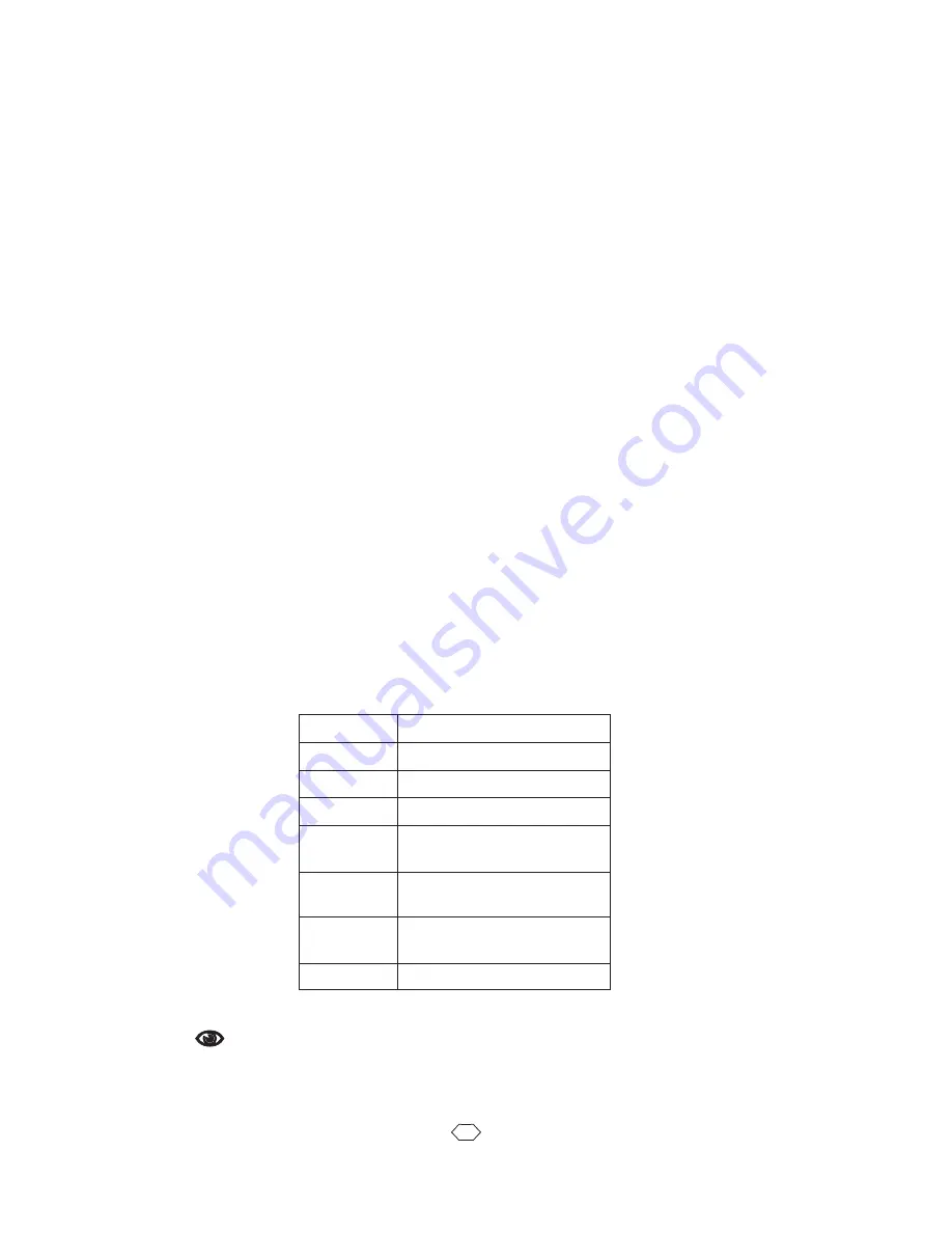
Refer
to
the
table
below
for
the
proper
value
to
use.
The
100%
motor
power
setting
only
applies
to
operation
in
jog
mode.
Under
program
control
the
“
S
”
and
“
S
A
"
speed
settings
set
power
to
motor.
m
NOTE:
CAUTION:
THE VXM MUST BE SET TO THE EXACT MODEL/TYPE MOTOR(S)
BEFORE OPERATING. IMPROPER SETTINGS CAN CAUSE
SEVERE
DAMAGE TO MOTORS
AND CONTROLLER.
See
Also
setMmMx, getMmM
x
Motor
Model
(Amps)
0
1
Default
(0.4A
to
$
Vexta
PK245
$
2
3
Slo-Syn
0
061
$
Slo-Syn
M062
$
Vexta
PK264
$
4
Slo-Syn
M063
$
Vexta
PK266
$
5
Slo-Syn
M091
$
Vexta
PK268
$
6
Slo-Syn
M092
(4.6A)
9H[WD3.$
VHW0$
P
0
[


