background image

Table of Contents

general

2

FCC
information

2

Specifications

3

Connection

3

Hardware
installation

4

Programming
Procedure

5

................................................................................................................................... 5

Writing/changing a program 

................................................................................................................................... 5

Compiling 

................................................................................................................................... 7

Actual programming of the microcontroller 

.......................................................................................................................................................... 9

Programming 

................................................................................................................................... 10

Erase pic device 

Experiments

11

ICSP

12

I

Contents

K8048 © 2003 Velleman Components

Summary of Contents for K8048

Page 1: ...K8048 2003 Velleman Components K8048 PIC PROGRAMMER BOARD ...

Page 2: ...nic kits Our range goes from easy to build Mini Kits to more advanced Kits such as High End audio circuits domotic systems and computer interface kits Because of the huge success of our sophisticated measuring instruments like the PC and hand held oscilloscopes we ve founded the Velleman Instruments division The Velleman Kit team ...

Page 3: ...cations 3 Connection 3 Hardware installation 4 Programming Procedure 5 5 Writing changing a program 5 Compiling 7 Actual programming of the microcontroller 9 Programming 10 Erase pic device Experiments 11 ICSP 12 I Contents K8048 2003 Velleman Components ...

Page 4: ...ogrammed in the processor via the K8048 by means of the PICPROG2 software The K8048 has room available for the direct mounting of 4 different footprints 8 pins 14 pins 18 pins and 28 pins Other footprint types can also be used via the ICSP connector This addition allows the use of controllers with different connections or controllers mounted in a device The latter can be programmed without removin...

Page 5: ... reprogrammed up to 1000 times Software is included to compile and program your source code Power 12 or 15V DC min 300mA non regulated adapter PS1205 PS1208 PS1508 230Vac PS1208USA 115Vac IBM compatible PC Pentium or higher with Windows 95 98 ME NT 2000 XP CDROM and a free serial RS232 port cable not included e g CW014 Supports these FLASH microcontrollers PIC12F629 PIC12F675 PIC16F83 PIC16F84 A P...

Page 6: ...when working with the K8048 e g executive programs for other programmers measuring devices PDA s etc Place selector SW5 in the central position standby Connect a non regulated 12 to 15V DC adapter of min 300mA with the K8048 via SK1 compatible Velleman adapters PS1205 PS1208 PS1508 230Vac or PS1208USA 115Vac The POWER LED LD7 should now be the only one to light indicating that the power supply of ...

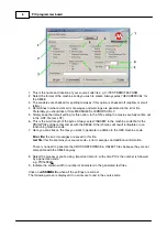
Page 7: ...to machine language In this instance the Microchip PIC assembler software MPASMWIN EXE is used Programming the machine code is programmed in the processor via your PC and the K8048 using the PROGPIC2 EXE software Erase pic device erasing the contents of a controller 6 1 Writing changing a program In order to write or modify a program Velleman K8048 Examples DEMOF627 ASM Example of a program treate...

Page 8: ...INHX8M in the machine code file for the PROGPIC2 software that comes with the K8048 Other choices will result in illegible or non functioning machine code 7 Here you can click on the files you want to generate in addition to the HEX machine code Error file the error messages are saved in this file List file this file contains your source code error messages and additional information There is no n...

Page 9: ...d the additional remarks generated by the assembler xxx COD Code file is only used by the MPLAB programming environment and NOT by the K8048 software 6 3 Actual programming of the microcontroller Connect your K8048 with your computer via a free serial port The IRQ line of this erial port IRQ 3 or 4 must not be used by another device e g internal modem Connect the suitable power adapter and verify ...

Page 10: ...mming 6 LOW VOLTAGE Programming does not apply to the K8048 All controllers are programmed with a programming voltage VPP of 13 and not 5V 7 Select the microcontroller you are using The included microcontroller belongs to one of the two following types PIC16F627 of PIC16F627A Make sure you have selected the right type number 8 Normally speaking the configuration of the controller is identified wit...

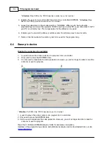
Page 11: ... buttons and diagnostics LEDs under Experiments Put SW5 in the RUN position to test the program if it was written to be used with the test push buttons and LEDs 1 Press this button to read out a program and data from a controller provided the latter is not code protected PIC s for which the code protection bit has been activated can no longer be read out only erased which automatically means that ...

Page 12: ... the memory and to be used for the programming 6 4 Erase pic device Erasing the contents of a controller 1 Is used to erase the entire contents of a program from a controller 2 Only used to erase the EEPROM data 3 Can be used to deactivate the code protection However you will no longer be able to read the contents or use the program Attention Put SW5 in the PROG position to use this function 1 Is ...

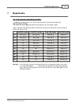
Page 13: ...t 28 pin PIC socket LD1 GP2 pin 5 RC0 pin 10 RB0 pin 6 RA0 pin 2 LD2 GP4 pin 3 RC1 pin 9 RB1 pin 7 RA1 pin 3 LD3 NC RC2 pin 8 RB2 pin 8 RA2 pin 4 LD4 NC RC3 pin 7 RB3 pin 9 RA3 pin 5 LD5 NC RC4 pin 6 RB4 pin 10 RA4 pin 6 LD6 NC NC RB5 pin 11 RA5 pin 7 SW1 GP5 pin 2 RC5 pin 5 RA0 pin 17 RB0 pin 21 SW2 NC RA2 pin 11 RA1 pin 18 RB1 pin 22 SW3 NC NC RA2 pin 1 RB2 pin 23 SW4 NC NC RA3 pin 2 RB4 pin 25 ...

Page 14: ...isting of four or five wires viz the ICSP bus Several members of the PIC family can be programmed or reprogrammed without having to remove them from the print or deactivating the power supply These IC s are converted to programming mode by applying the programming voltage of 12 to 14V to the MCLR pin From this point onwards RB6 is used as a CLOCK input while RB7 is modified into a DATA input outpu...

Reviews: