H7200-ED2-27
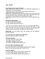
C11 and C12, 220nF MKM (sometimes with annotation u22)
C13 and C14, 470nF MKM (sometimes with annotation u47)
Assembling the voltage regulator:
Fold the connections of the voltage regulators at right angles and Mount them on
to the board. Fiw them by means of M3 bolt and nut; then solder the
connections.
VR1 type 7805; VR2 type 7905
Mount the elco's C15 and C16 of 1000uF
on the solder side
of the board and
lay them flat on to the board surface; then the connect-ions can be soldered and
snipped off on the component side. Pay attention to polarity!
Mount the ICs type 7107 in their socket with the peak facing C15 and C16.
Mount the displays DY1 and DY6 (see board annotation)
Mount the six boardpins for Va and Cs
on the solder side
.
CHECK ALL COMPONENTS THOROUGHLY YET AGAIN!
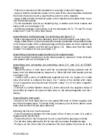
CONSTRUCTION
- Supply the ends of the heatsinks with thread by means of the additionally
supplied 25mm long zinc-plated bolt (see figure 2.0). This screw-thread is used
for fixing the front and back panel.
- Mount the bottom plate on the heatsinks by means of the rubber feet and
12mm bolts and nuts (first mount the four feet on the bottom plate, then slide the
nuts in the slots and fix) (figure 8.0)
- Mount the back cover of the heatsinks (with four black M4 nuts which are not
zinc-plated), in such a way that the large openings are situated in the top right-
hand corner (when viewed from behind). (figure 8.0)
- On the back cover, mount by means of 35mm long bolts, lock washer and nut,
the fan with blowing direction outward (the blow direction is indicated on the fan
by means of an arrow). Supply a nut between the back cover and the fan to the
2 upper openings (see figure 2.1)
- Mount the fuse holder and the power plug by means of zinc plated M3 bolts
with lock washer and nut.
Assembling the transistors type TIP3055:
REMARK: when assembling the transistors the easiest way to tackle the
problem is to put the housing upright.
-Slide the transistor board with connections for three transistors into the slot of
the right heatsink (see figure 3.2) in such a way that the connections for the
transistors are situated on the appropriate positions (see figure 3.0).
- Slide the other transistor board into the left heatsink (see figure 3.1)
- Slide hexagonal socket bolts in the fastening slot of the heatsinks and position
them on the spot where the transistors are to come. (see figure 3.4)
Summary of Contents for K7200
Page 2: ......
Page 3: ...INDEX GEBRUIKSAANWIJZING 4 MODE D EMPLOI 13 OPERATING INSTRUCTIONS 23 GEBRAUCHSANWEISUNG 32 ...
Page 42: ...H7200 ED2 42 ...
Page 43: ...H7200 ED2 43 ...
Page 44: ...H7200 ED2 44 ...
Page 45: ...H7200 ED2 45 ...
Page 46: ...H7200 ED2 46 ...
Page 47: ...H7200 ED2 47 ...
Page 48: ...H7200 ED2 48 ...
Page 49: ...H7200 ED2 49 ...
Page 50: ...H7200 ED2 50 ...
Page 51: ...H7200 ED2 51 ...
Page 52: ...H7200 ED2 52 ...
Page 53: ...H7200 ED2 53 ...
Page 54: ...H7200 ED2 54 ...


