DVM645BI GB
18
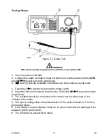
6. The resistance of the test leads can diminish accuracy in the lowest (400
Ω
)
range. The error is usually 0.1 to 0.2
Ω
for a standard pair of test leads. To
determine the error, short the test leads together and the use the
Relative
mode to automatically subtract the lead resistance from the resistance
measurement.
7. After all measurements have been completed, disconnect the test leads from
the circuit and multimeter input terminals.
The Continuity (
) measurement is as follows:
1. Select the continuity measurement by pressing the
button.
2. Insert the black and red test leads into the
COM
and
V
Ω
Ω
Ω
Ω
Hz
input terminals
respectively.
3. Connect the black and red test probes to the circuit or device under test. First
make sure that the circuit or device is dead.
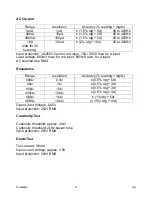
4. An audible tone will sound when the resistance is less than approximately
40
Ω
.
5. After the continuity measurement has been completed, disconnect the test
leads from the circuit and multimeter input terminals.
6. The continuity measurement is always fixed range. Open circuit voltage is
approximately 0.45V.

