background image

- 17 - 

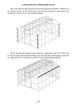
7. Mounting of Cellular polycarbonate (CP) on the roof  


Warning! 

When installing the CP, it is important that the CP cellular lines be on the roof 

along the arcs, and on the side walls - vertically.  

The parts "D" with the size of 2100x3250mm are used for mounting. 

7.1.

 Start the installation of the CP sheets on the roof from the end-faces. Place the 

CP on the roof so that the sheet protrudes (hangs over) about 5 cm beyond the edge 
of the end-face over the door. The side edges of the CP (with open cellular) should not 
protrude  over  the  edge  of  the  side  wall,  so  the  CP  will  need  to  be  trimmed  after 
installation. 

7.2.

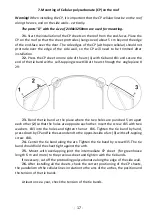
 Press the CP sheet on one side of the arc (1) with tie band #31 and secure the 

end of the tie band with a  self-tapping screw #38 at the arc through the  angle piece # 
29: 


7.3. 

Bend the tie band  at the place where the two holes are punched 5 cm apart 

each other (

2

) so that the holes are opposite each other. Insert the screw  #35 with two 

washers  #33 into the holes and tighten the nut  #36. Tighten the tie band by hand, 
press down by CP and fix the second end to the opposite side of arc (

3

) with self-tapping 

screw  #38. 

7.4. 

Center the tie band along the arc. Tighten the tie band by screw #35. The tie 

band should hold the sheet tight against the arch. 

7.5. 

Mount  with  overlapping  joint  the  intermediate  CP  sheet    (for  greenhouse 

length  6 m and more) to the previous sheet and tighten with the tie bands.  

If necessary, cut off the protruding polycarbonate along the edge of the side wall. 

7.6. 

After installing all the sheets, check the correct positioning of the CP sheets, 

the parallelism of the cellular lines in relation to the arcs of the arches, the position and 
the tension of the tie bands. 

 
At least once a year, check the tension of the tie bands. 


Summary of Contents for MAGNOLIA

Page 1: ...GREENHOUSE MAGNOLIA Made of 1 x1 25x25mm steel galvanized profile tube...

Page 2: ...2...

Page 3: ...3 Width 10 3m Height 7 2 1m Base length 13 4m Extension on 6 5 2m...

Page 4: ...art Name Q ty BASE Q ty EXTEN Picture 1 A B End face half arch left hand 1605mm 2 2 A B End face half arch right hand 1605mm 2 3 End face lintel top 960mm 2 4 Doorway post left hand 2055mm 2 5 Doorway...

Page 5: ...mm 2 22 Door post right hand 1780mm 2 23 Air gate lintel top bottom 850mm 4 24 Air gate post left hand 470mm 2 25 Air gate post right hand 470mm 2 26 Side diagonal tie 600mm 4 27 Longitudinal startin...

Page 6: ...onate The end faces and the framework intermediate arches are connected by six longitudinal stringers To exclude the slope of the framework end faces under wind loads end face diagonal ties are provid...

Page 7: ...and 2B Secure the connection with self tapping screws 37 2 on each side The assembly will result in an end face arch of the roof 2 2 Secure the left hand doorway post 4 and right hand doorway post 5...

Page 8: ...s 37 2 5 Connect the middle part 11 of the bottom transverse rib to the left and right parts and simultaneously attach the left 4 and right 5 doorway posts to them Secure the connections with self tap...

Page 9: ...ts 4 5 and the bottom lintel 10 12 setting the angle of 90 with a try square 2 7 Use self tapping screws 37 to attach the jib sticks 8 to the side posts 7t and the roof end arch 2 8 Install the four e...

Page 10: ...crews 37 in the corner of the door way on the inside 2 10 Using parts 18 22 and self tapping screws 37 assemble the doors Use a try square to ensure correct geometry when assembling The door post 22 w...

Page 11: ...27 with hinge holes should be on the right hand side 2 11 Insert the air gate in the door secure with two hinges 42 using screws 35 and nuts 36 Secure the upper hinge of the door to the upper hinge of...

Page 12: ...ur self tapping screws 37 two on each side 3 2 Using the assembled end face as a template place the assembled arch and posts 7 on it one of the 7mm holes in the posts should be at the bottom Connect t...

Page 13: ...te arches to the stringers 28 with bolts 32 through the drilled holes 4 5 Fasten the second end face with bolts 32 for the length of greenhouse 4 m To extend the greenhouse by 2 m use kits consisting...

Page 14: ...rew the bolt 32 that secures the bottom stringer to the side post insert the leg into the post from below until the holes match secure the leg with the bolt 5 3 Install the legs in all the other posts...

Page 15: ...the part A of CP to the end face door by aligning the bottom edge of CP along the bottom lintel of the end face Fasten part 1 with self tapping screws 38 through thermal washers 39 according to the sc...

Page 16: ...the right middle end face lintel and fix the mating hinge of the door so that the door holder secures the door in the open position 6 8 Insert the hand lever from the kit 40 into the 12 holes on the d...

Page 17: ...ce 29 7 3 Bend the tie band at the place where the two holes are punched 5 cm apart each other 2 so that the holes are opposite each other Insert the screw 35 with two washers 33 into the holes and ti...

Page 18: ...of the CP to the end post 8 2 Using self tapping screws 38 through the thermal washers 39 fasten the CP to the side posts and longitudinal stringers according to the scheme of fixing the polycarbonate...

Page 19: ...the framework 8 self tapping screws per angle piece thus closing the vertical corner joints of polycarbonate 9 2 Using 38 self tapping screws mount four angle pieces 29 120 2025 mm to the joint polyca...

Page 20: ...e framework and that the tie bands are not displaced from the arches After compacting the ground make sure that the tie bands are not offset to the sides and are along the arches Correct if necessary...

Page 21: ...remove all sheets of cellular polycarbonate from the arched part of the greenhouse the greenhouse roof by removing tie bands The advantage of sheets removing for winter is that the snow gets inside t...

Page 22: ...rve you for decades under proper usage in the design without prior notice to the consumer The products are not subject to mandatory certification Due to the continuous improvement of Magnolia products...

Page 23: ...23...

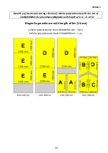
Page 24: ...e of cellular polycarbonate with the size of Magnolia greenhouse with length of 4m 1 base Cellular polycarbonate sheet 2100 6000 mm 3 pcs Cellular polycarbonate sheet 2100 4000 mm 1 pc 2100x6000mm for...

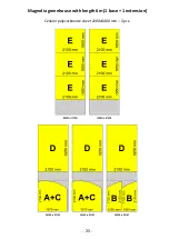
Page 25: ...25 Magnolia greenhouse with length 6m 1 base 1 extension Cellular polycarbonate sheet 2100 6000 mm 5 pcs...

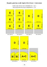
Page 26: ...26 Magnolia greenhouse with length of 8m 1 base 2 extensions Cellular polycarbonate sheet 2100 6000 mm 6 pcs Cellular polycarbonate sheet 2100 2000 mm 1 pc...

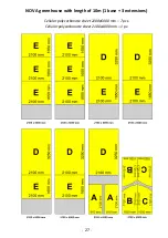
Page 27: ...27 NOVA greenhouse with length of 10m 1 base 3 extensions Cellular polycarbonate sheet 2100 6000 mm 7 pcs Cellular polycarbonate sheet 2100 4000 mm 1 pc...

Reviews: