


[Figure 5-20. Audio] [Figure 5-21. Relay]
[Figure 5-22. Text]
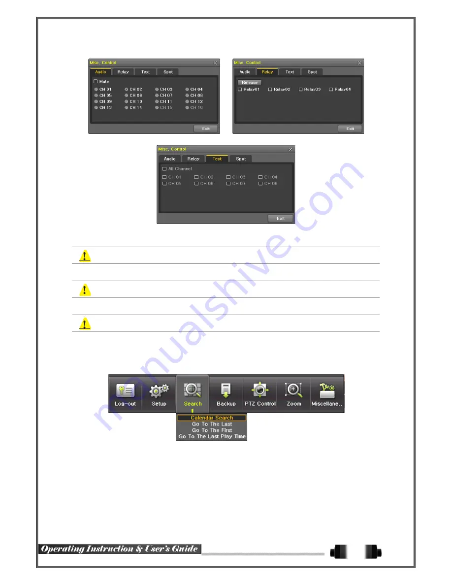
①
Move to the Audio tab and select the channel to be activated or Mute.
SVR-1648D1 model supports 16 channel audios
②
Move to the Relay tab and select.
SVR-1648D1 model supports 4 channel input
③
Move to the TEXT tab and select.
SVR-1648D1 model supports 1-16 channel text input
5
-
6
Search
5
-
6
-
1
Search Mode
Move to
{Menu} {Search}
in the real-time monitoring mode.
[Figure 5-23. Playback Menu]
5
-
6
-
2
Playback Menu
(1) Calendar Search
Calendar Search allows the user search and playback by [Year/Month/Day/Hour/Minute],[Multi-Channel/Multi-
Time/Multi-Day]and [Motion/Sensor/Audio/Pattern].
(2) Go To The Last
The user can search and playback the last recorded data by Multi-Channel Mode.
(3) Go To The First
The user can search and playback the first recorded data by Multi-Channel Mode.
30