background image

27 


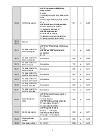
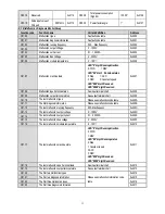
F11.04 

Feedback signal filter time 

0.000

6.000s 

0.010s 


0xB04 

F11.05 

Feedback signal gain 

0.00

10.00 

1.00 


0xB05 

F11.06 

Given and feedback range 

0

100.0 

100.0 


0xB06 

F11.07 

PID control selection   

LED”0” digit: Feedback feature selection 

0: Positive feature    1:Negative feature 

LED”00”/”000” digit: Reserved 
LED”0000” digit: Differential adjustment 
properties 

0: Differential bias                                       
1: Differential of feedback 

0100 


0xB07 

F11.08 

PID preset output 

0.0

100.0% 

100.0% 


0xB08 

F11.09 

PID preset output running 
time 

0.0

6500.0s 

0.0s 


0xB09 

F11.10 

PID control deviation limit 

0.0

100.0% 

0.0% 


0xB0A 

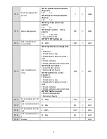
F11.11 

Proportional gain P1 

0.000

8.000 

0.100 


0xB0B 

F11.12 

Integral time I1 

0.0

600.0s 

1.0s 


0xB0C 

F11.13 

Differential time D1 

0.000

6.000s 

0.000s 


0xB0D 

F11.14 

Proportional gain P2 

0.000

8.000 

0.100 


0xB0E 

F11.15 

Integral time I2 

0.0

600.0s 

1.0s 


0xB0F 

F11.16 

Differential gain D2 

0.000

6.000s 

0.000s 


0xB10 

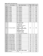
F11.17 

PID Parameter switching 
condition 

0: No switch                         
1: Use DI terminal to switch 
2: Switch according to deviation 


0xB11 

F11.18 

Low value of switching 
deviation 

0.0

100.0% 

20.0% 


0xB12 

F11.19 

High value of switching 
deviation 

0.0

100.0% 

80.0% 


0xB13 

F11.20 

Reserved 


0xB14 

F11.21 

Differential limit 

0.0

100.0% 

5.0% 


0xB15 

F11.22 

PID output upper limit 

0.0

100.0% 

100.0% 


0xB16 

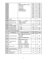
F11.23 

PID output lower limit 

-100.0

F11.19 

0.0% 


0xB17 

F11.24 

PID output filter time 

0.000

6.000s 

0.000s 


0xB18 

F11.25 

Feedback wire break 
detection time 

0.0

120.0s 

1.0s 


0xB19 

F11.26 

Feedback wire break action 
selection 

0: Go on PID operation without alarm 
1: Stop and alarm malfunction 
2: continue to PID operation and output alarm 
signal 
3: Run at the current frequency and output 
alarm signal 


0xB1A 

F11.27 

Wire break alarm upper limit 

0.0

100.0% 

100.0% 


0xB1B 

F11.28 

Wire break alarm lower limit 

0.0

100.0% 

0.0% 


0xB1C 

F11.29 

Close-loop suspend detection 
threshold 

0.0

100.0% 

0.0% 


0xB1D 

F11.30 

Close-loop suspend detection 
time 

0.0

600.0s 

1.0s 


0xB1E 


Summary of Contents for AC300 Series

Page 1: ...2018...

Page 2: ...Chapter 3 Keyboard layout and functions specification 8 Chapter 4 Function Parameter Table 9 4 1 Basic parameters 9 4 2 Terminal of Input and Output Function Selection 30 4 3 Monitor Code 31 4 4 Faul...

Page 3: ...pection and maintenance please cut off power supply of all related equipment s and ensure main DC voltage in safe range And please operate it after 5 mins Power wire motor wire and control wire should...

Page 4: ...860 540 325 55 200 110 63 38 560 990 600 365 75 260 150 86 52 630 1100 680 400 90 320 180 98 58 710 1260 760 450 1 3 Technical criterion Items Criterion Power input Voltage frequency Three phase 380V...

Page 5: ...munication given and multi channel terminal selection Main and auxiliary channel combination expansion card supporting different modes switch Feedback input channel Voltage CurrentTerminalAI1 Voltage...

Page 6: ...B AC300 T3 R75G 1R5P B 76 200 192 155 149 65 65 193 5 5 4 3 M4 AC300 T3 1R5G 2R2P B AC300 T3 2R2G B AC300 T3 004G 5R5P B 100 242 231 155 149 84 86 5 231 5 8 5 5 3 M4 AC300 T3 5R5G 7R5P B AC300 T3 7R5G...

Page 7: ...er Steel MODEL Overall Dimension mm Installation Aperture W H D H2 W1 H1 AC300 T3 045G 055P 225 523 290 500 176 509 7 AC300 T3 055G 075P 225 523 290 500 176 509 7 AC300 T3 075G 090P 240 570 340 535 17...

Page 8: ...r MCCB PUL 24V PLC COM Analog Voltage Current quantity input A B RS485 Differential Communication 120 Open collector OC state output Analog Voltage Current quantity input 2 Symbol Note 1 When installi...

Page 9: ...ransistor connection mode External power supply E X5 X3 X4 X2 X1 PLC 24V Enabled external 24V power supply COM COM Enabled inner 24V power supply 24V PLC X1 X2 X4 X3 X5 Shield Cable E External control...

Page 10: ...arameter in modify state Modify given frequency ID given while at standby or monitoring state While given frequency PID are set by keyboard and F4 09 needs to be set Run key While run stop is controll...

Page 11: ...communication control 3 Reserved 0 0x002 F00 03 Frequency given source channelA 0 Keyboard number given 1 Reserved 2 Voltage Current analogAI1 given 3 Voltage Current analogAI2 given 4 Reserved 5 Ter...

Page 12: ...0x00B F00 12 Lower limit frequency 0 00 upper limit frequency 0 00Hz 0x00C F00 13 Lower limit frequency running mode 0 Stop output enter into pause running state 1 Run at lower limit frequency 1 0x00D...

Page 13: ...10C F01 13 Reserved 0x10D F01 14 DC braking hold time when stop 0 0 60 0s 0 0s 0x10E F01 15 Stop detection frequency 0 00 50 00Hz 0 50Hz 0x10F F01 16 ACC DEC selection LED 0 digit time base selection...

Page 14: ...to function table 4 2 5 0x203 F02 04 Input terminal 5 X5 Refer to function table 4 2 6 0x204 F02 05 Input terminal 6 X6 expand Refer to function table 4 2 0 0x205 F02 06 Input terminal 7 X7 expand Re...

Page 15: ...requency corresponding setting 0 00 100 00 0 00 0x21D F02 30 PULinput max frequency 0 00 50 00 KHz 50 00kHz 0x21E F02 31 PULmaxfrequency corresponding setting 0 00 100 00 100 00 0x21F F02 32 PULfilter...

Page 16: ...ction table 4 2 0 0x23A F02 63 Virtual vX4 terminal function selection Refer to function table 4 2 0 0x23B F02 64 vX terminal valid state source 0 internal connection with virtual vYn 1 Connect with p...

Page 17: ...al function 0 0x30C F03 13 AI1 high level setting 0 00 100 00 70 00 0x30D F03 14 AI1 low level setting 0 00 100 00 30 00 0x30E F03 15 AI2 function selection See Xterminal function 0 0x30F F03 16 AI2 h...

Page 18: ...2 F03 35 Curve 2 upper limit 0 00 10 00V 10 00V 0x323 F03 36 Curve 2 upper limit corresponding setting 0 00 100 00 100 00 0x324 F03 37 A0 output signal selection LED 0 digit AO1 0 0 10V 1 4 00 20 00mA...

Page 19: ...ameter and key locked 0 0x400 F04 01 User password 0 65535 0 0x401 F04 02 F04 04 Reserved F04 05 Parameter copy 0 No function 1 Send inverter parametersto keyboard and save 2 Send keyboard parameterst...

Page 20: ...content of the first line in stop state Same as above 1100 0x410 F04 17 The display content of the first line in stop state Same as above 0402 0x411 F04 18 The display content of the second line in ru...

Page 21: ...ndom PWM valid 0 Prohibited 1 Valid LED 0000 digit PWM modulation mode 0 Only use three phase modulation 1 Two phase and three phase modulation automatically switched 1111 0x421 Motor Parameters NO Fu...

Page 22: ...n LED 0 digit closed loop vector 0 OFF 1 ON 2 On only operate firstly when electrify LED 00 digit open loop vector 0 OFF 1 ON 2 ON only operate firstly when electrify 0010 0x515 F05 22 F05 29 Reserved...

Page 23: ...4 000 1 000 0x60B F06 12 Current loop Q axis proportional gain 0 001 4 000 1 000 0x60C F06 13 Current loop Q axisintegral gain 0 001 4 000 1 000 0x60D F06 15 Vector control motor slip compensation 0 0...

Page 24: ...Optional card 0 0x701 F07 02 Torque keyboard number setting 0 100 0 0 0 0x702 F07 03 Torque input lower limit 0 100 00 0 00 0x703 F07 04 Lower limit corresponding setting 200 00 200 00 0 00 0x704 F07...

Page 25: ...100 0 100 0 0x809 F08 10 Self setting frequencyF05 0 00 maxfrequency 50 00Hz 0x80A F08 11 Output voltage percentage 25 0 120 0 100 0 0x80B F08 12 Torque boost 0 0 30 0 0 0 0x80C F08 13 Torque boost c...

Page 26: ...rrent according to itswaveform 0 off 1 on LED 00 digit OC protection interference suppression 0 off 1 First grade 2 Second grade LED 000 digit SC protection interference suppression 0 off 1 First grad...

Page 27: ...ge 2 Detected load is too large only at constant speed 3 Detected underloaded 4 Detected underloaded only at constant speed LED 00 digit Alarm selection 0 alarm and continue operation 1 Fault protecti...

Page 28: ...150 0 110 0 0xA1B F10 28 Stall detection time 0 000 2 000s 0 010s 0xA1C F10 29 Motor overshot Protection threshold extend 0 200 C 0xA1D F10 30 Motor overshot Pre alarm threshold extend 0 200 C 0xA1E F...

Page 29: ...gain D2 0 000 6 000s 0 000s 0xB10 F11 17 PID Parameter switching condition 0 No switch 1 Use DI terminal to switch 2 Switch according to deviation 0 0xB11 F11 18 Low value of switching deviation 0 0...

Page 30: ...e unit 0 second 1 minute 2 hour LED 000 digit Power down memory 0 Not save 1 save LED 0000 digit Start mode 0 Restart fromthe 1st stage 1 Restart fromthe stop stage 2 Continue running from the time wh...

Page 31: ...ising time 0 00 650 00s 5 00s 0xC36 F12 55 Swing frequencyfalling time 0 00 650 00s 5 00s 0xC37 Communication Control Function Parameter Group NO Function description Range of setting and definition F...

Page 32: ...Specification X Function Specification X Function Specification 0 No function 16 19 Multispeed terminal 1 4 41 Timer clear terminal 1 FWD 20 PID control cancel 42 Counter input terminal 2 REV 21 PID...

Page 33: ...putAO1 0 01V 0 01m A 0 01kHz 0x2114 C00 01 Output frequency 0 01Hz 0x2101 C00 21 Analog outputAO2 extend 0 01V 0 01m A 0 01kHz 0x2115 C00 02 Output current 0 1A 0x2102 C00 22 Counting value of counter...

Page 34: ...on output terminal status See output terminal chart 0x2209 C01 10 The last malfunction types Please see malfunction code table 0x220A C01 11 The first diagnosis information Please see malfunction code...

Page 35: ...heat 16 Inverter overheat 17 External fault 18 74 RS485 communication abnormal 19 Current detection fault 20 Motor detection fault 21 69 Storage fault 25 Motor detection fault 26 Parameter copy abnorm...

Page 36: ...otor or the inverter and has lasted for a period Make sure whether it overload and whether the machine model is right Periodic overhaul Under normal state one overhaul every 3 or 4 months is ok Please...

Page 37: ...confirm that the main circuit DC voltage has declined to the security level Perform relevant operation after 5 minutes 5 2 Maintenance All equipments and components have useful life Right maintenance...

Page 38: ...00 or 0x2000 0 60 000 is corresponding to 0 00Hz 600 00Hz W R Communication Command Setting 0x3001 or 0x2001 0000H No order W R 0001H FWD running 0002H REV running 0003H FWD jog 0004H REV jog 0005H DE...

Page 39: ...n code table While using writing command 06 H if the highest digit of parameter function code addressdomain is 0 it only write in the RAM of inverter and on storage when power off if the high half dig...

Page 40: ......
Reviews: