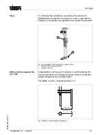
weight solids
,
turn the potentiometer to the left stop
(
>
0
.
008
g
/
cm
³
or
0
.
0003
lbs
/
in
³
).
VEGAWAVE
63
will thus be more
sensitive and can detect light
-
weight solids more reliably
.
F
or instruments detecting solids in water
,
these values are not
applicable
.
T
he potentiometer is preset and must not be
changed
.
T
he characteristics reversal can be carried out with the
DIL
switch
.
Y
ou can choose between falling characteristic curve
(
switch position max
.)
and rising characteristic curve
(
switch
position min
.).
T
his allows you to output the desired current
.
M
odes
l
min
. -
rising characteristic curve
(
H
igh current when
immersed
)
l
max
. -
falling characteristics
(
L
ow current when immersed
)
T
he
NAMUR
output can be switched over to falling or rising
characteristics
(
see also
"
F
unction chart
"
).
T
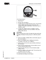
he simulation key is located in a recess on the upper side of
the oscillator
.
P
ush the simulation key with a suitable object
(
screwdriver
,
pen
,
etc
.).
W
hen the key is pushed
,
a line break between sensor and
processing unit is simulated
.
T
he signal lamp on the sensor
extinguishes
.
T
he measuring system must signal a fault and
take on a safe condition when the key is pushed
.
K
eep in mind that the connected instruments will be activated
during operation
.
T
his allows you to check the correct function
of the measuring system
.
C
ontrol lamp
(
LED
)
for indication of the switching status
.
l
yellow
=
H
igh current
≥
2
.
2
m
A
l
dark
=
L
ow current
≤
1
m
A
l
yellow
(
fl
ashing
)
=
F
ailure
≤
1
m
A
6
.
3
F
unction chart
VEGAWAVE
63
level switch
T
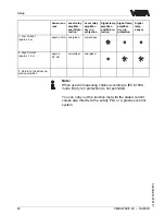
he following chart provides an overview of the switching
conditions depending on the adjusted mode and level
.
N
ote
:
T
he mode setting on the
NAMUR
ampli
fi
er must be selected in
such a way that the switching output takes on safe condition in
case of failure
(
I
<=
1
m
A
).
C
haracteristics reversal
(
2
)
S
imulation key
(
3
)
S
ignal lamp
(
6
)
VEGAWAVE
63
- -
NAMUR
21
S
etup
32259
-
EN
-
070117


